
Narrowband SDR transceiver - phase 1
|
SummaryAn attempt to make a new compact and flexible transceiver for amateur radio use. |
Introduction
After getting involved in the student satellite project NUTS and a stratospheric glider platform in the Edge of Space 2 project, a search was initiated to find a radio that could be used as an experimental SDR payload and as a telemetry radio in these applications. Such a radio should typically fullfill the following demands:- Small size, low weight and low power consumption
- High sensitivity narrow band receiver
- Output power in the order of 5 watts and high efficiency at reduced power levels
- Software implemented (de)modulation of 1200 baud AFSK and 9600 baud GMSK modes, as well as analog modes (FM/AM/SSB)
- A wide set of ports for digital communication (UART/SPI/I2C) and D/A- and A/D-converters for analog audio
- Fast TX<->RX switcing time
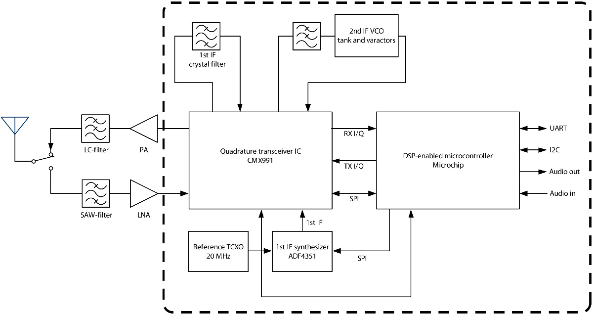
The following block schematic shows the final layout.
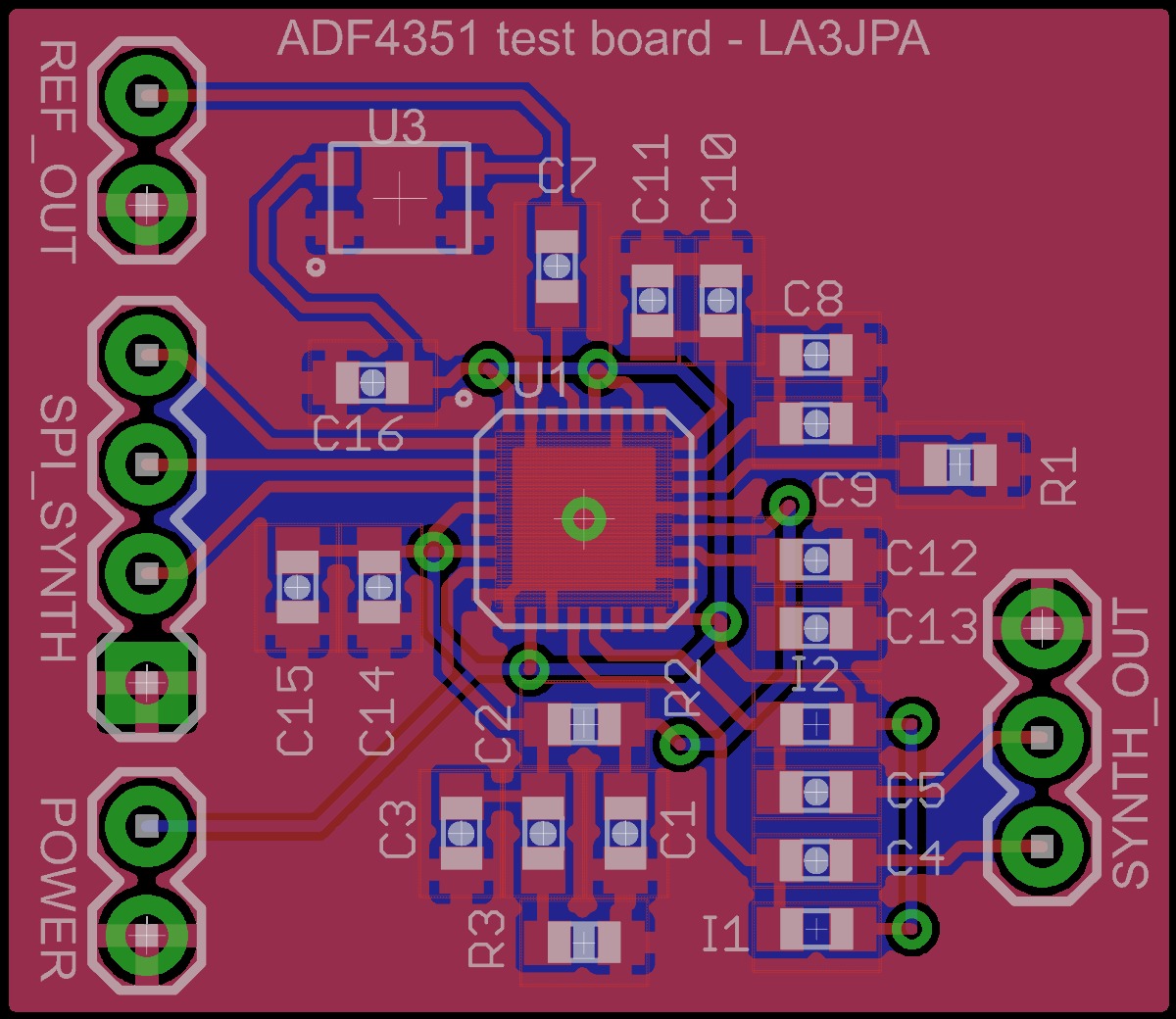
Synthesizer board
The first local oscillator signal is provided by an Analog Devices ADF4351. A simple two-layer PCB was made to test the circuit. After configuring the registers properly, it was operating well. Very little phase noise was observed, but some fairly strong odd harmonics were present.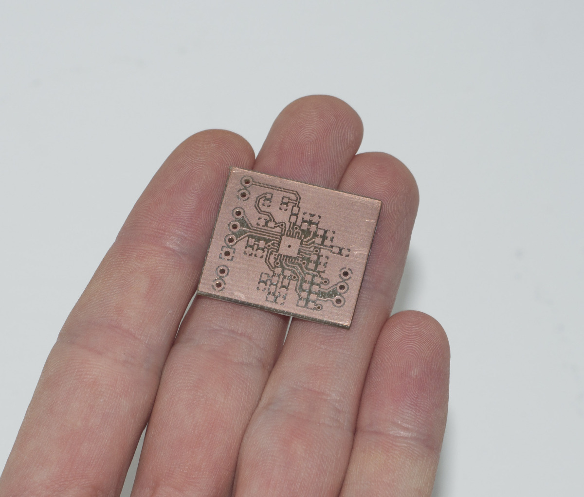


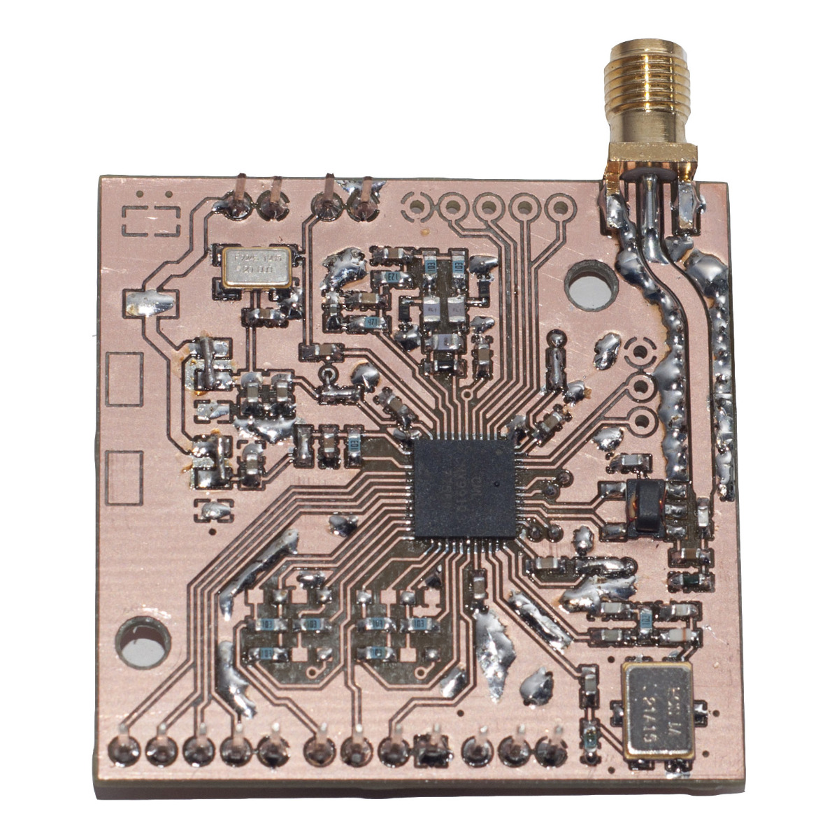
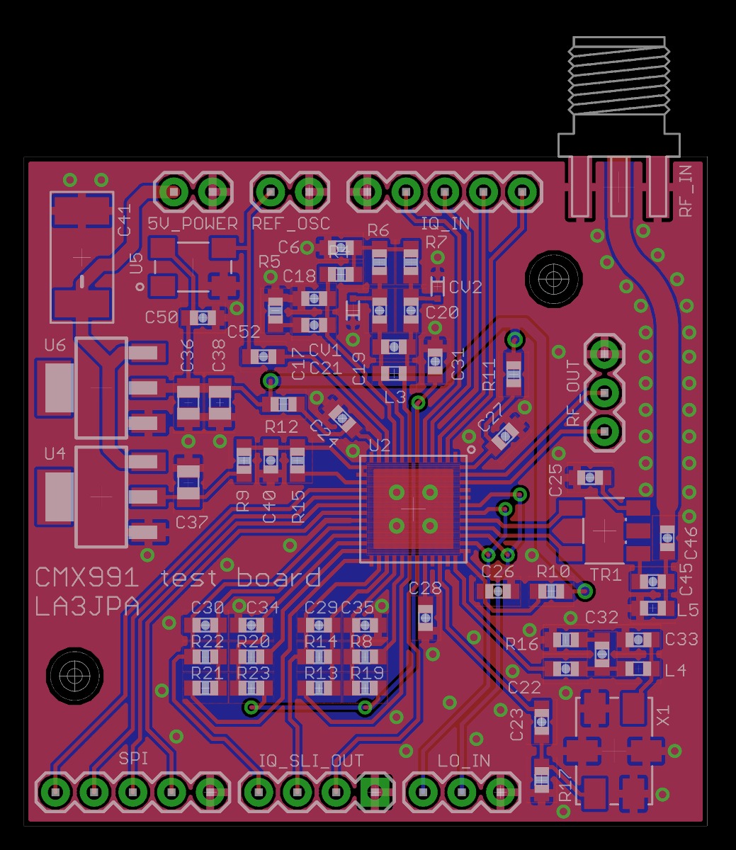
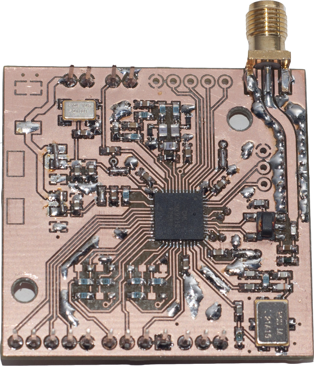
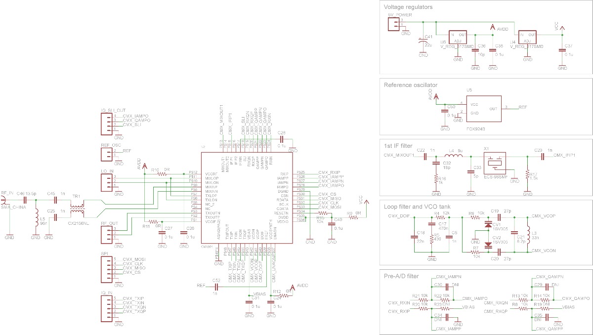
Transceiver board
The CML CMX991 transceiver IC was tested on a two-layer PCB. The RF-input was converted to single ended with a 1:1-transformer, and the matching network was primarily calculated for maximum S21 at 145 MHz. Second priority was to maximize S21 at 435 MHz.Much thought was put into the matching circuit of the IF-section to minimize loss, but still provide sufficient termination load for harmonics from the mixer. A standard 21.4 MHz crystal filter was used.
A 20 MHz temperature compensated crystal oscillator provides the reference, with a stability of +/- 2.5 PPM over the whole operationg temperature range.

Complete receiver prototype
The two circuit boards, a power supply and a dsPIC microcontroller was mounted in a plastic box and tested. The software demodulation algorithm is explained with a block schematic below. Note that SSB-demodulation is done with adding and subtracting the quadrature components directly, whereas a good implementation should include phase shifting the quadrature component 90 degrees (a Hilbert transform) before adding or subtracting. The voice recording below reveals that this simplification works very bad, and should be reimplemented.


Some testing
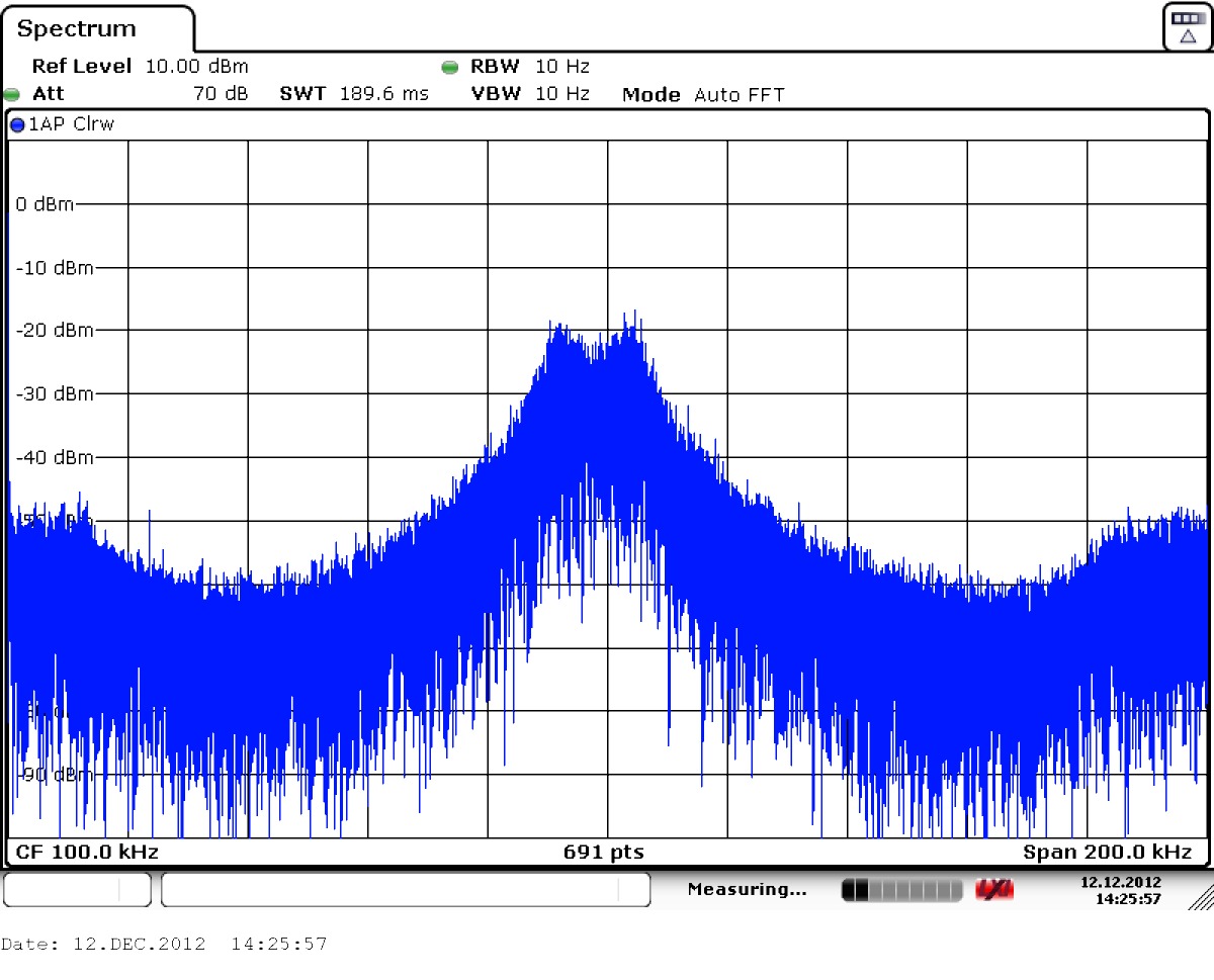
Three tests were done. First, it was desireable to see if all mixers and local oscillator worked properly. A -50 dBm @ 144.725 MHz carrier was applied to the input. The first local oscillator was tuned so the signal would appear at 21.4 MHz in the first IF, and the second oscillator was tuned to 21.3 MHz so the signal would appear in baseband at 100 KHz. The plot belows shows a well downconverted signal in baseband, at 100.058 KHz.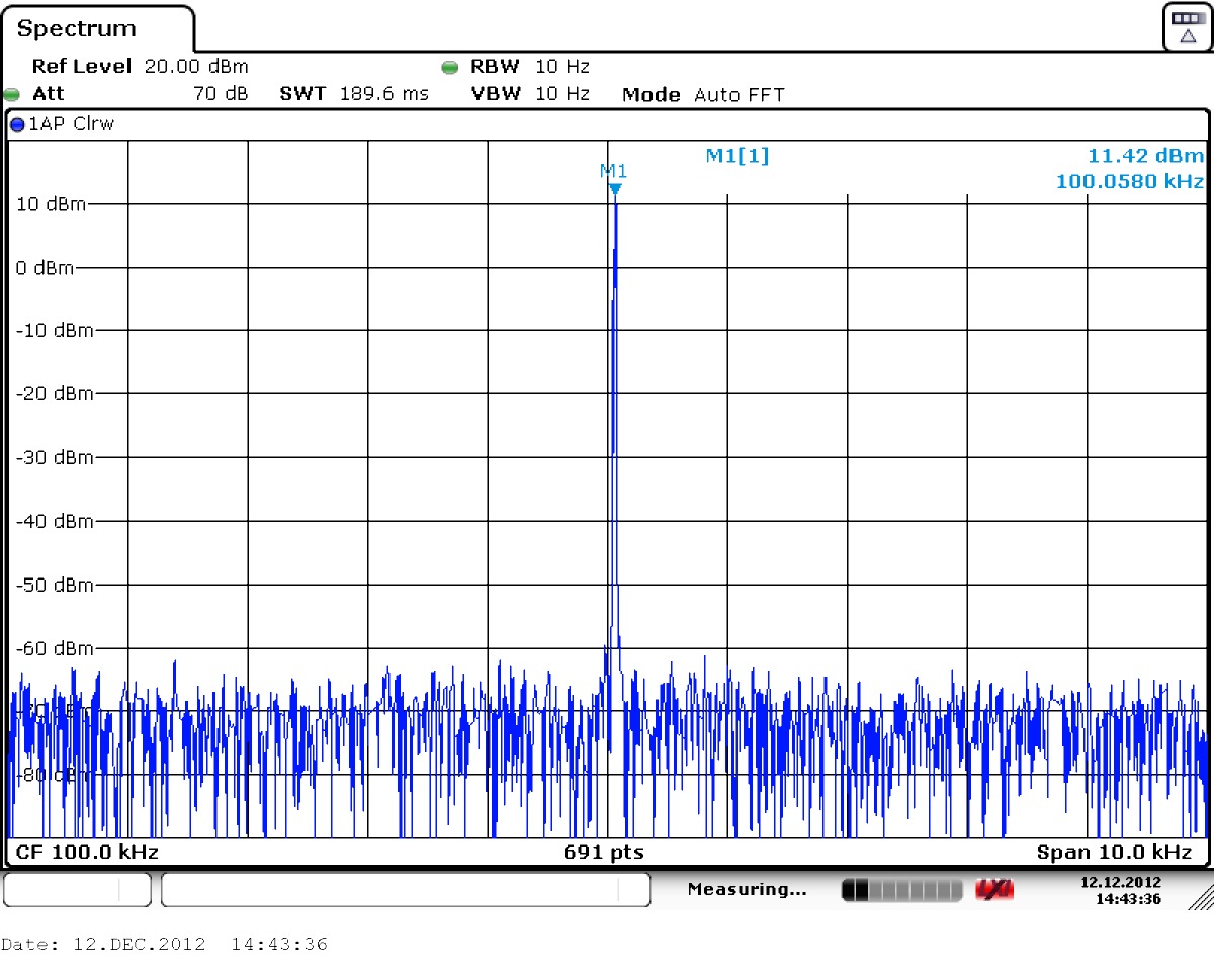
The second test was to measure the response of the IF-filter. The vector generator was set to output white noise, but otherwise the same setup as above was used.
The third and final test was to try demodulation with voice transmitted from a standard Yaesu FT-897D HF-rig. The result can be downloaded here: