
Raspberry Pi Zero PLC for home automation
|
SummaryA small PLC-like unit for home automation based on a Raspberry Pi Zero that can be mounted on a DIN rail in a fuse box. |
Introduction
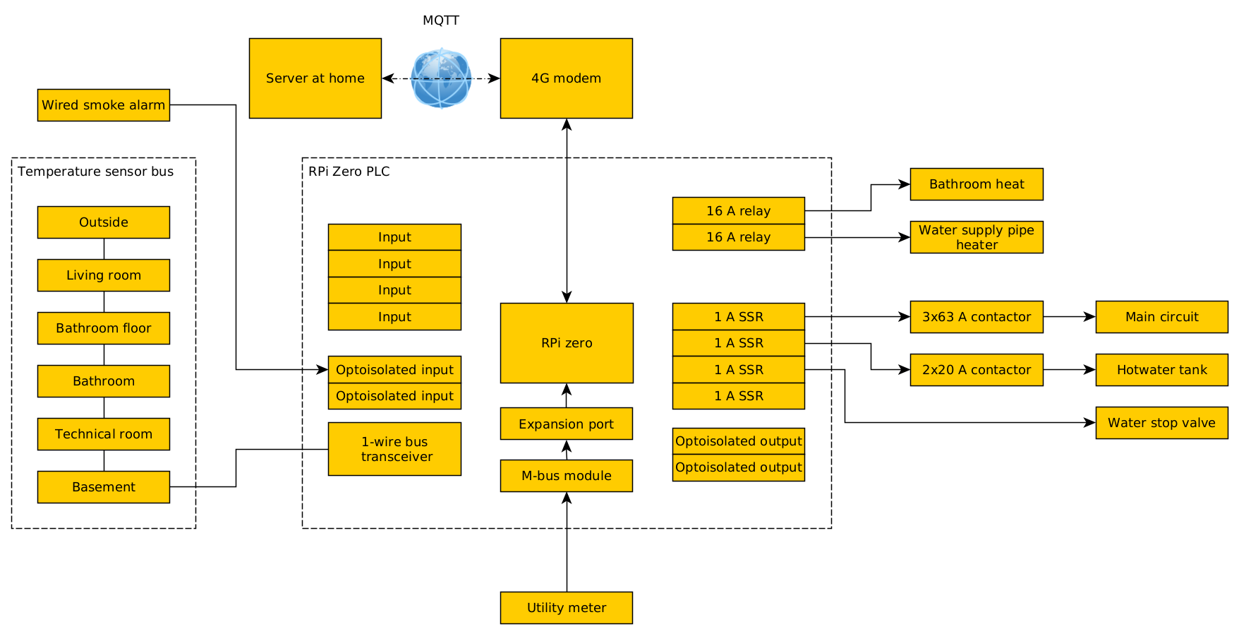
Unlike my home, which has about 50 separate CAN bus nodes scattered around the house, I wanted a compact and simple solution to control and monitor our cabin. What I ended up with is a small unit based on a Raspberry Pi Zero that can be mounted on a DIN rail.- All sensors are wired to maximize stability and avoid the need to replace batteries (important because the cabin is a remote location).
- The Raspberry Pi runs a very minimal software setup, and only does what really needs to run locally and can't handle an internet outage (like the thermostat logic).
- All logs with significant activity are written to RAM, to minimize flash wear.
- The Raspberry Pi connects to my server using MQTT through 4G.
- The server runs an MQTT broker and an additional instance of Home Assistant in a docker container
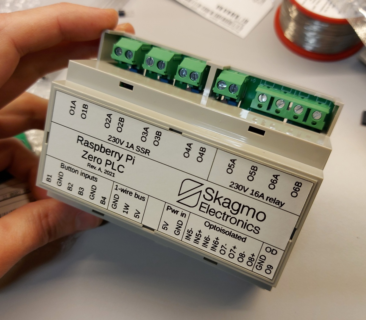
Hardware specifications
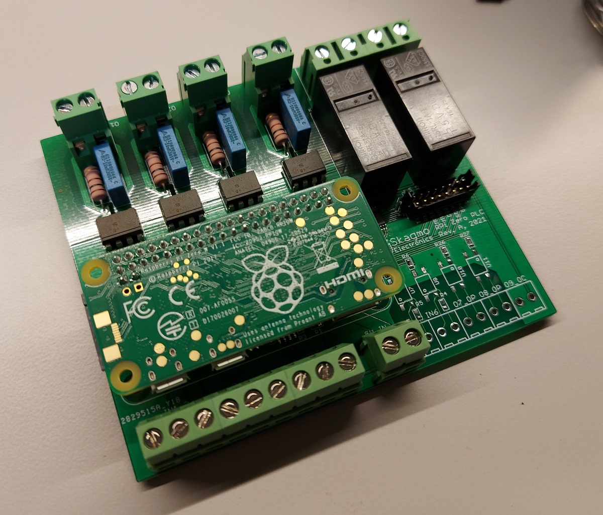
- Raspberry Pi Zero socket
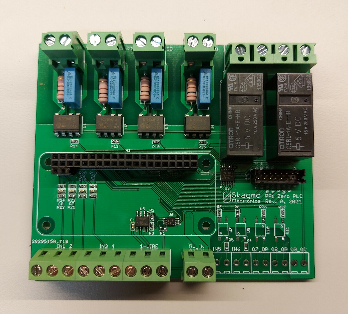
- 2 x 16 A 230 VAC Omron relays that can handle inductive loads with large inrush current
- 4 x 1 A 230 VAC solid state relays with external snubber circuits, primarily intended to control contactors (and other small but inductive loads)
- 4 x inputs with pull-up and filtering
- 2 x optoisolated inputs
- 2 x optoisolated outputs
- 1 x open collector output
- 1-wire bus transceiver (DS2482) to maximize range for a DS18B20 temperature sensor bus
- Expansion port with M-bus slave (for meter reading)
Software
For the cabin application I've written a Python program which:- Sends all sensor values and states over MQTT
- Accepts setpoints for thermostats and output states over MQTT
- Implements thermostats
- Reads 1-wire sensor bus (DS18B20), M-bus (and parse the messages), and inputs (with debouncing)
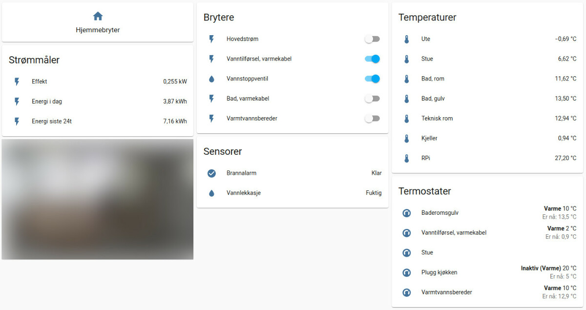
The remote control works really snappy, and it's nice to know that all states are acknowledged. (When I turn on a switch and see that it's on, it reflects the actual state of the output.)