
Behringer Flow 8 teardown
|
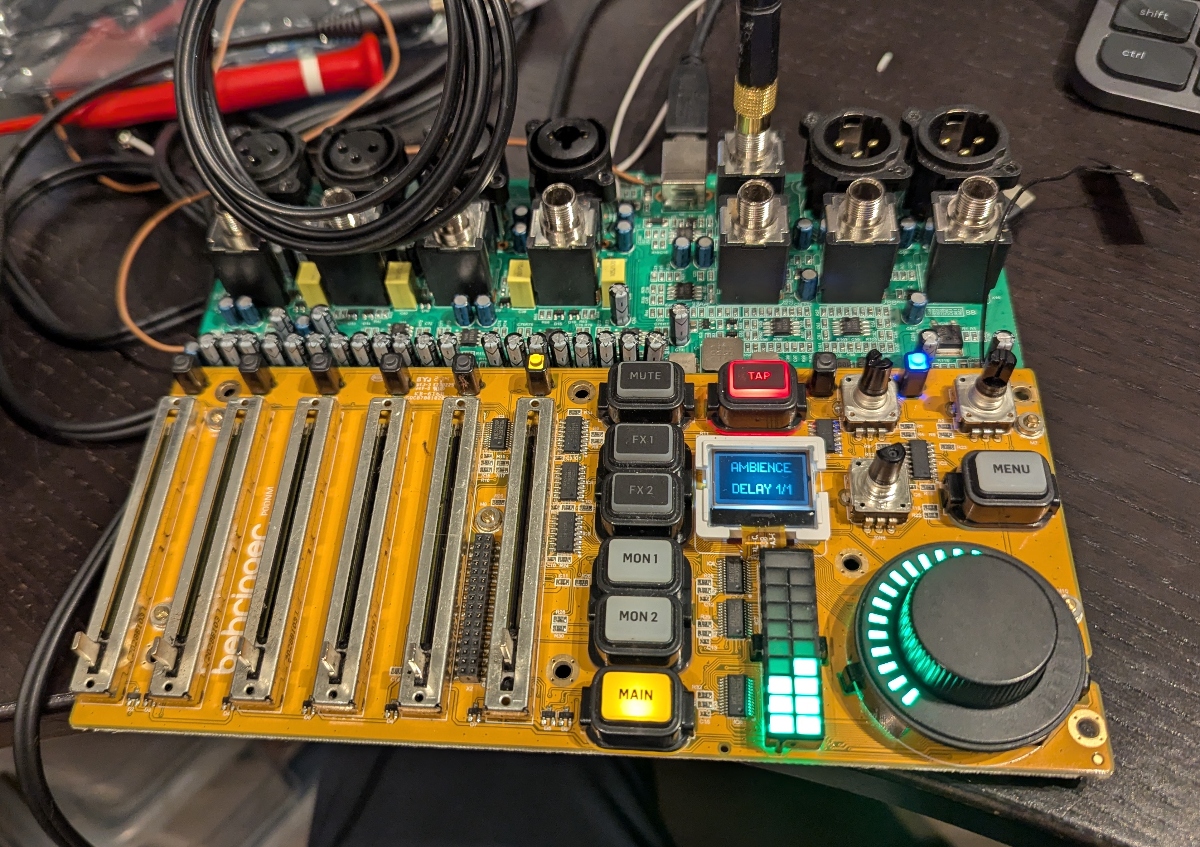
A look into the internals of the Behringer Flow 8, which in my opinion is a good and extremely cheap digital mixer. |
Technical details
Main components:
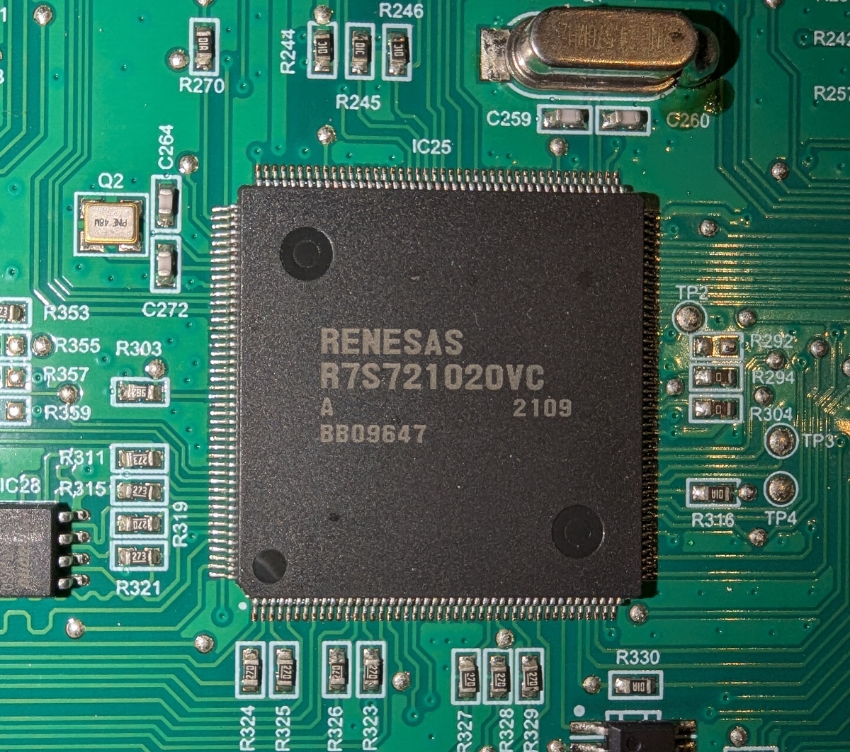
- MCU: Renesas R7S721020VC, ARM Cortex-A9 @ 400 MHz
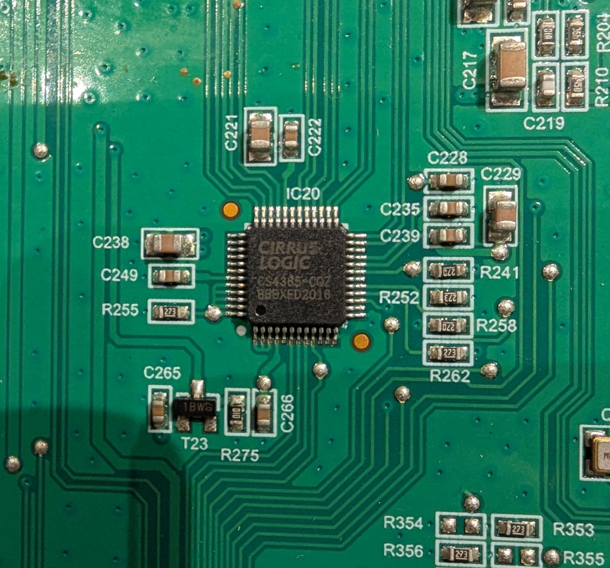
- DAC: Cirrus Logic CS4385-CQZ, 8 channel, 114 dB SNR, 24 bit, 192 KHz
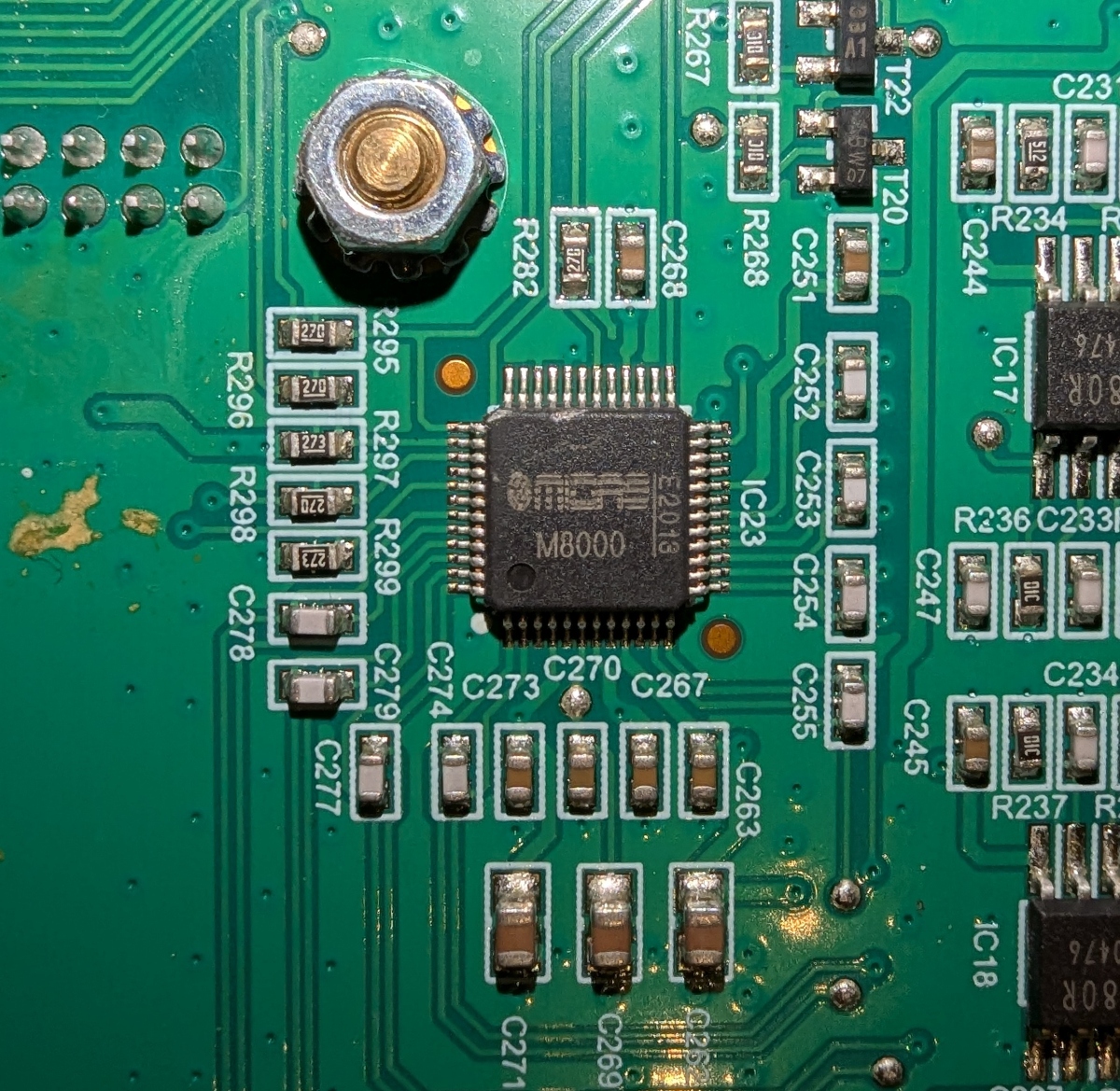
- ADC: Midas M8000, 8 channels, 115 dB SNR, 24 bit, 192 KHz
"Fake" balanced outputs
Unfortunately, the Flow 8 doesn't have proper balanced outputs. I couldn't see the cold signal being driven, and sure enough, negative/cold was only connected to ground through a capacitor and resistor. Quite a lot of flux residues left as well...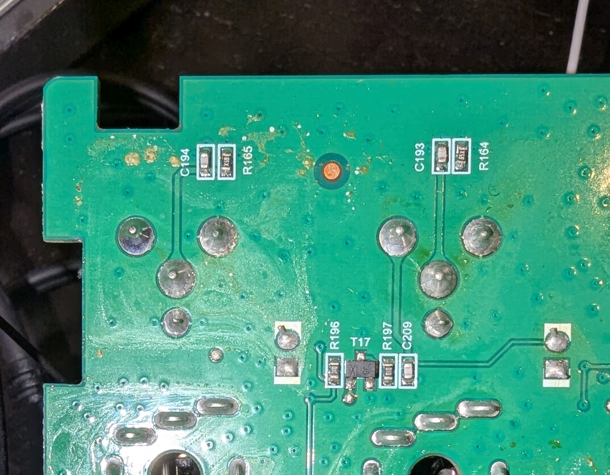
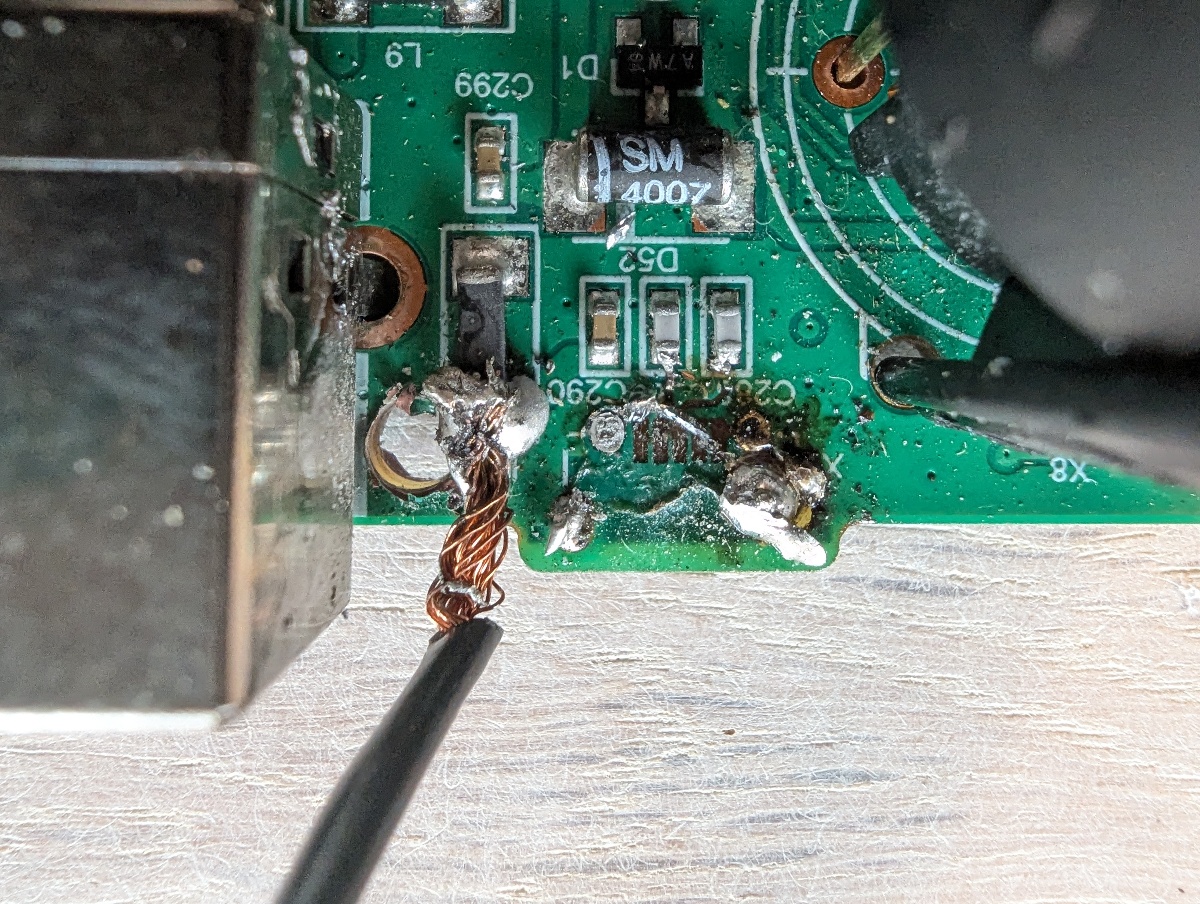
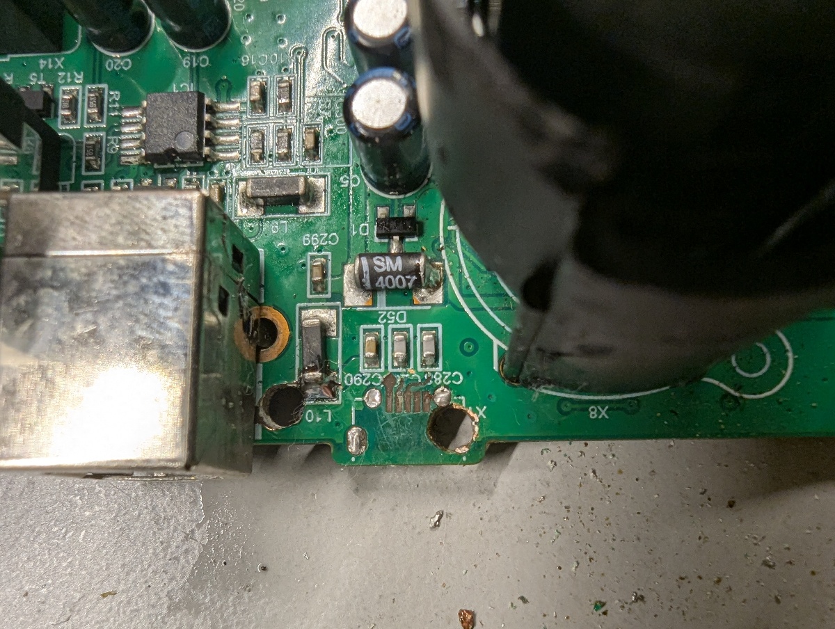
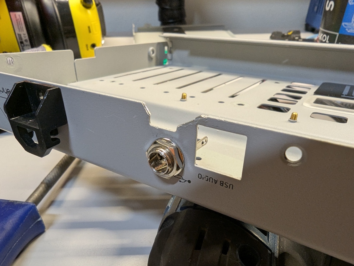
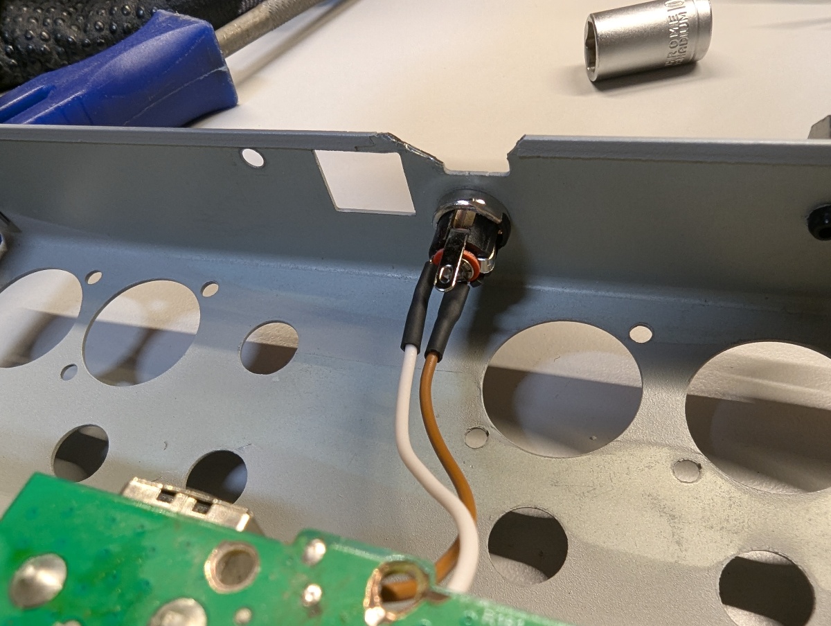
Fix micro USB power input
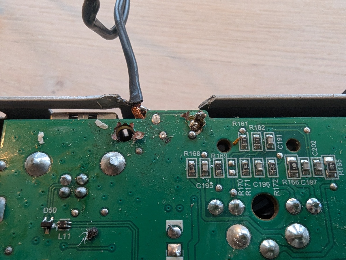
I bought the mixer used (and non-working), and as many others, the previous owner had broken the fragile micro USB connector and tried to fix it. I cleaned up and used a panel mount DC barrel jack instead.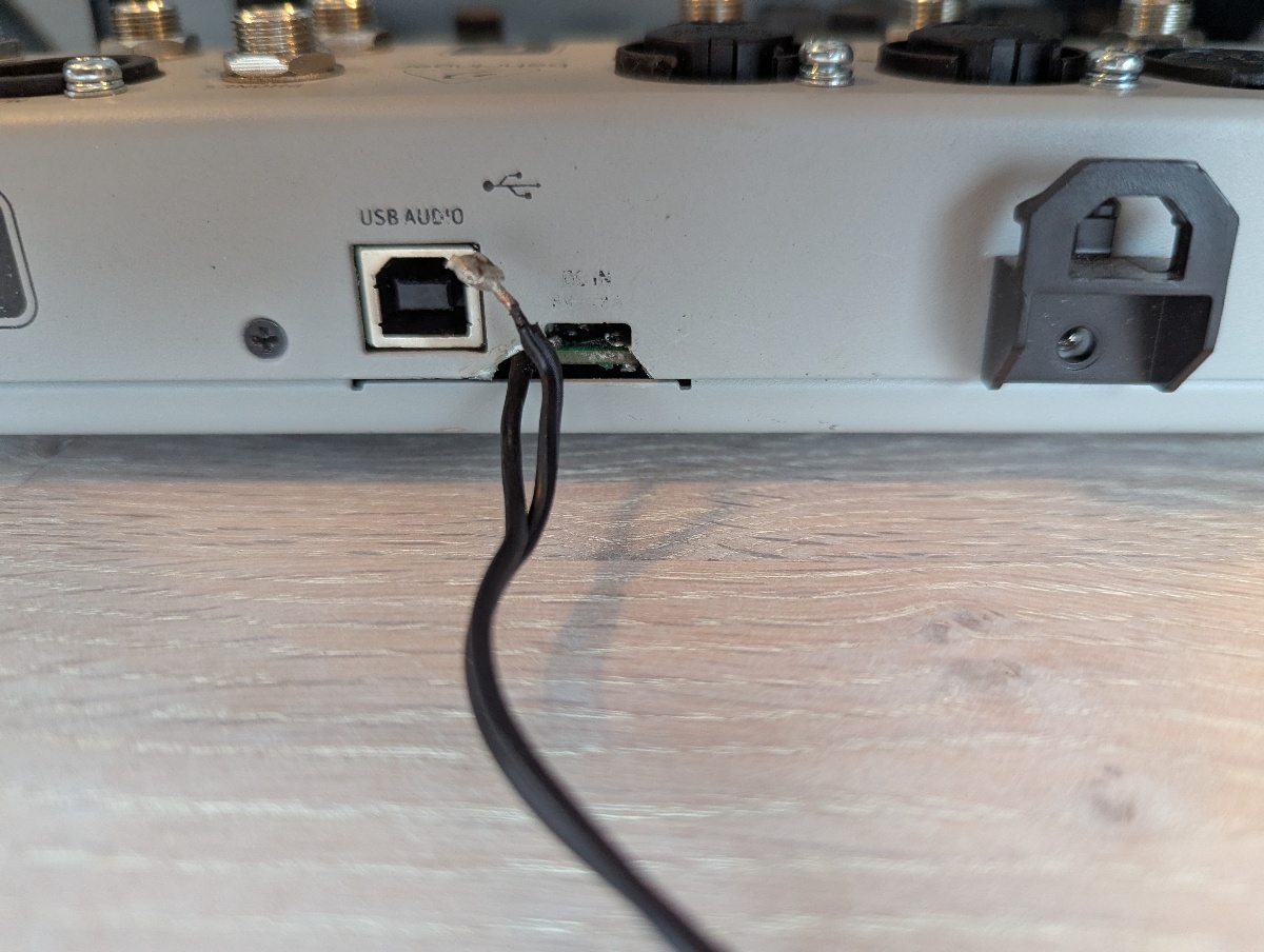
Bluetooth audio quirks
The Bluetooth audio functionality in the Flow 8 is great to have. Unfortunately it has two issues:- The bluetooth audio device name appears blank: My Pixel 8 phone doesn't show the device and I can't connect. However, the fix is simple. Go to "Settings" -> "System" -> "Developer options" -> "Show Bluetooth devices without names" and enable it.
- Audio codec is limited to SBC: Flow 8 doesn't support aptX (HD) or similar, only the basic SBC codec. SBC dynamic range is quite poor, and you will hear the difference from a wired connection or a better codec like aptX.
Adding AES/EBU or S/PDIF output
Adding a digital output means we have to connect to the interface between the MCU and the DAC. Superimposing the pinout from the datasheet on top of an image of the PCB reveals how the DAC is configured: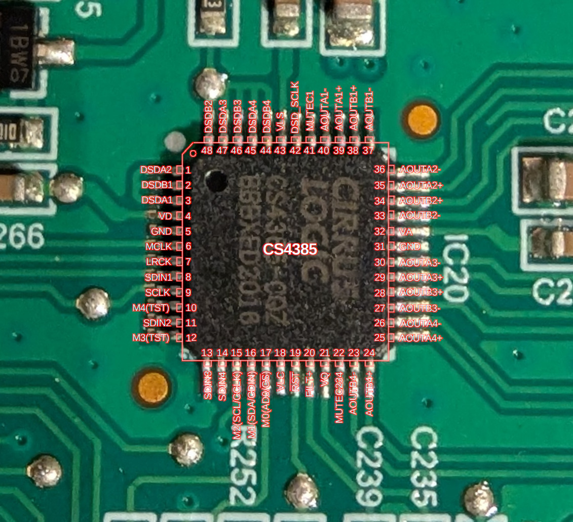
We can see that SDIN2-4 is unconnected, and only SDIN1 is used. This means Behringer chose to use the TDM format, which has only one data line for all channels (and much higher data clock). I was hoping for the interface between the MCU and the DAC to be standard I2S with four data lines. Fair enough, but it doesn't make it easy to use a standard S/PDIF transmitter like Texas Instruments DIT4192.
There are four signals; MCLK, SCLK, LRCK and SDIN. The master clock from MCU to DAC, MCLK, is observed with an oscilloscope to be ~24.57 MHz.
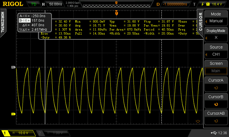
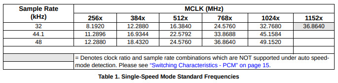
This matches well with a sample rate of 48 KHz and MCLK running at 512x rate, single speed mode, which would be 24.576 MHz:
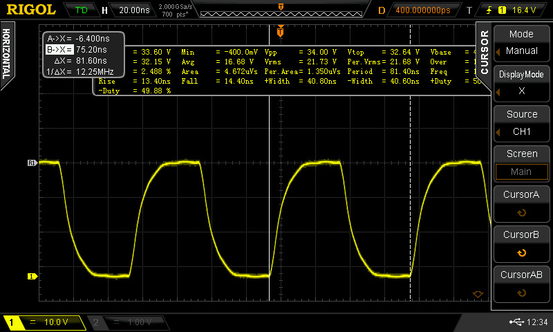
The serial data clock, SCLK, is expected to be running at Fs * ch * bit_per_channel = 48 KHz * 8 * 32 = 12.288 MHz
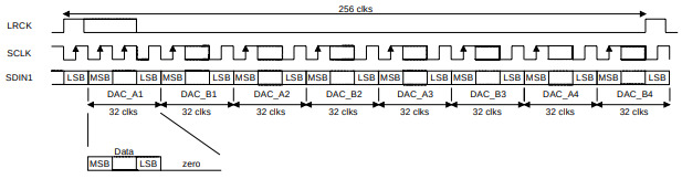
Sure enough, we measure ~12.25 MHz:
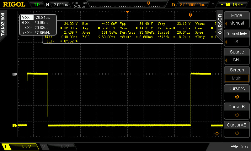
Similarly, LRCK, which in TDM mode is used to indicate the start of a new frame, runs at 48 KHZ:
Adding an S/PDIF output could be done by using a MCU:
- Receive TDM data with SPI peripheral running as framed SPI slave, and extract 2 of the 8 channels
- Transmit S/PDIF using another SPI peripheral clocked at 48 KHz * 16 bit per channel * 2 channels * 2 (manchester coding) = 3.072 MHz.
- Using MCLK as a clock source for the MCU makes it easy to divide the system clock by 8 to obtain a nearly jitter-free S/PDIF signal