
eSmart3 MPPT PV charger review

|
SummaryThe eSmart3 is an extremely affordable high power MPPT charger. You can get the 40 A (~2 kW) version for about 110 USD including shipping on Aliexpress. It has "advanced" features such as an RS-485 port for remote readout and control, and can be used with battery packs up to 48 V. In this review I'll take a closer look at the hardware and performance. |
Hardware
The maximum ratings are as follows:| PV voltage | 150 V |
| Battery voltage | 60 V |
| Charge current | 40 A |
With a battery pack of 48 V nominal, that corresponds to about 2 kW. The relatively high maximum PV voltage is nice to be able to reduce the current (and wire gauge) from your PV array.
Components
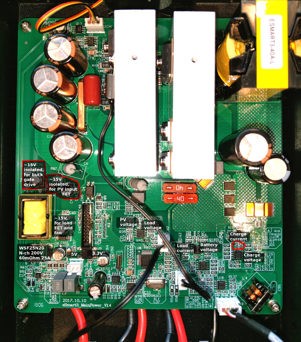
More details about the design is added in an update on the bottom of the review.
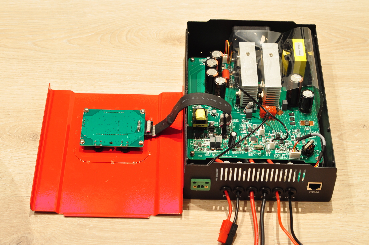
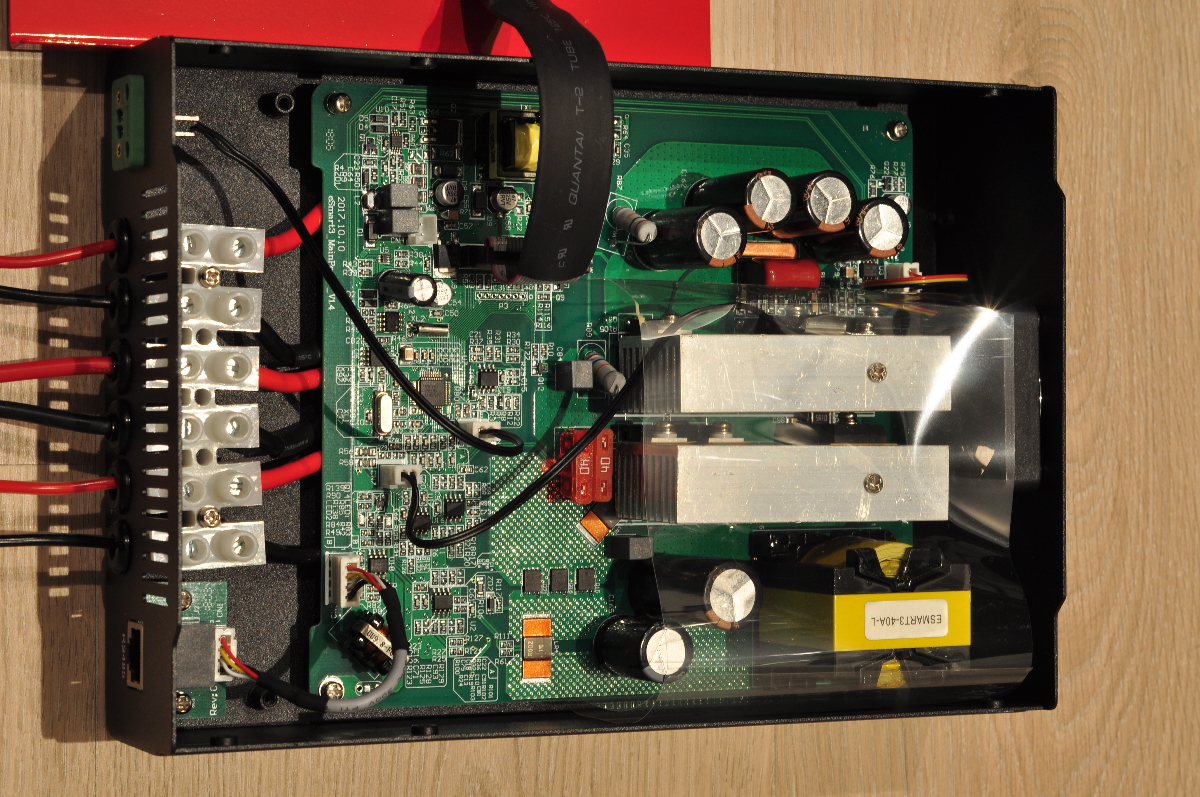
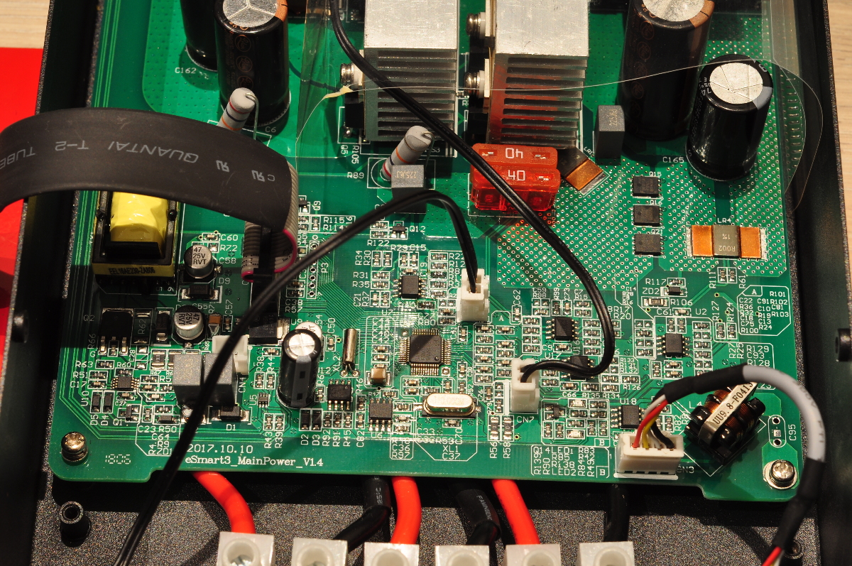
| Microcontroller | TI TMS320F2802 |
| PV/switching FET | 2 x IRFP4668 (8 mΩ, 200 V, 130 A) |
| Main FET gate driver | Si8220 |
| Load FET | 3 x FDMS037N08B (3.01 mΩ, 100 A, 75 V) |
| PV side caps | 3 x 220 uF, 160 V |
| Battery side caps | 1 x 2200 uF, 63 V (and another smaller one *) |
| Shunt amplifiers | TI LVM358 |
* The low side FET and the second output cap wasn't easy to read without further disassembly, and the inductor doesn't seem to be marked.
The components should likely be able to handle the power claimed. Be careful with the maximum battery voltage of 60 V, considering the caps are only rated for 63 V. 5% capacitor voltage margin is definitely a stretch. The switching frequency in the MPPT buck-converter is fixed at 50 KHz. Current is measured in (charge) and out (load) of the battery, but not on the PV side of the converter. How can this be shown in the display on the unit? Read further...
Performance
Efficiency
Let's first take a look at the efficiency with a single Axitec AC-275M/156-60S solar panel (275 Wp) and a 4S (14.8 V) LiPo battery, and see if it comes close to the claimed 98 % efficiency. Efficiency is measured by comparing power in and out of the charger with two Watt's Up meters which are accurate to within 1 %. The meters doesn't sample at the exact same time, so there's some noise in the readings as you can see.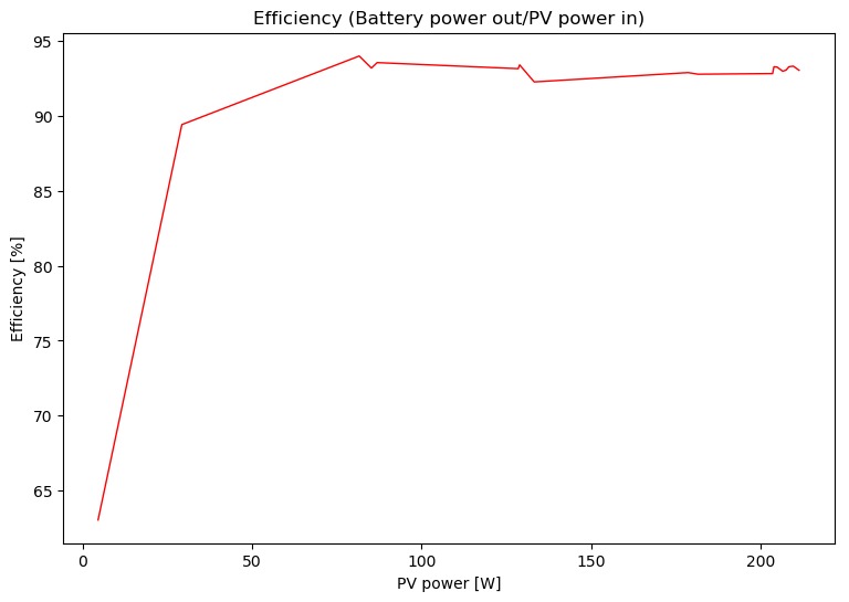
Not 98 %, but definitely not bad either. Keep in mind this was at power levels nowhere close to the maximum, but it's a good indicator of what you can expect.
Power consumption
At 1.5 W peak, the internal power consumption is probably not an issue for most people. A thermal camera reveals that the microcontroller is the main power consumer while the device is idle. It seems like the microcontroller never goes to sleep, which it definitely could have done.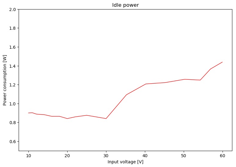
Measurement accuracy
One thing I noticed was the large deviation between measured values on the Watt's Up meters and the eSMART3. I confirmed this with a high quality Fluke multimeter which showed the same as the Watt's Up meters. The reference in the following plots is the Fluke multimeter: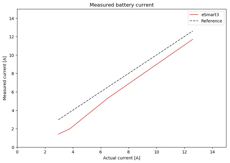
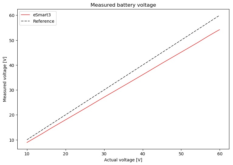
The displayed voltage seems to be 10 % lower than the reference (gain error), and the displayed current is approximately 1.5 A lower than the reference (offset error). Some money is probably saved by not calibrating every unit, but it would have been great to at least be able to set these values in firmware. Unfortunately it's not.
Due to this inaccuracy, be very careful when you set the voltage limits for your battery pack. Measure the actual voltage and compensate the values you set accordingly. Charging your LiPo cells to 10 % higher voltage than intended can be catastrophic (at least if you don't have a BMS to protect it).
Another strange feature of this thing is that the display shows PV voltage, power and current when it doesn't actually have a current shunt on the PV side. The ingenuity on this one is large; the engineers who wrote the firmware have simply set the PV power to be battery power + 1 %. The PV current is then calculated from the PV voltage and this "fictional" power reading. In other words, efficiency is always ~99 %...
Tracking
Overall it seems to find the maximum power point pretty quickly, but there is a serious issue: Especially when power increases slowly (during sunrise), it gets stuck on a low power/duty cycle and won't find the maximum power point. It can also happen randomly at a high power level. In that case, the PV panel needs to be disconnected and reconnected so the PV voltage will drop to zero. It will then track correctly again. Testing reveals this state is never recovered by itself, so manual disconnect/reconnect has to be done typically 2-3 times daily. This might have to do with my low PV voltage (approx. 30 Vmpp), so I'll appreciate feedback from people with multiple series connected panels with higher MPP voltage.The plot below shows power as a function of time through the day. A reset had to be done in the morning and in the middle of the day:
Conclusion
The eSMART3 has some firmware issues. Measured current and voltage is wildly inaccurate due to lack of calibration, and some values are simply made up, such as PV current (and power). This can be avoided by compensating for the error while setting voltage limits in the settings, and when receiving packets over RS-485. A more serious issue is that MPPT tracking fails and will not recover by itself. This might not apply to all setups. If this tracking issue can be resolved, the eSmart3 definitely gives you a lot for the money considering it's specifications. I haven't been able to test it at more than about 210 W, but judging from the components it can handle the full power. Typical efficiency is well above 90 %, which is pretty good.Extra: RS485 port
The pinout on this port is as follows:| Pin | Function |
|---|---|
| 1 | RS-485 A/+ |
| 2 | RS-485 B/- |
| 5,6 | GND |
| 7,8 | +5V out |
I hooked up an RS485 interface and tried the supplied Windows software "MyGreen Solar Monitor". Not very responsive, but it works to set parameters and read some values. I asked the seller for a protocol specification, but that was apparently not something they had, so I figured out it would be easier to reverse engineer the protocol. Port settings are 9600 baud, 8N1.
Example packet
| Byte # | Function | Example |
|---|---|---|
| 0 | Start byte | 0xaa |
| 1 | ? | 0x01 |
| 2 | Source address? (set in program) | 0x0b |
| 3 | Destination address? | 0x01 |
| 4 | Message type | 0x08 |
| 5 | Payload length (total length - 7) | 0x03 |
| 6 | Payload | 0x00 |
| 7 | Payload | 0x00 |
| 8 | Payload | 0x26 |
| 9 | Checksum, sum of all bytes excluding checksum | 0x18 |
Messages types
These are the most interesing ones:| Type | Content |
|---|---|
| 0 | Voltage, current, power, temperature, battery SoC, "reduced CO2" |
| 2 | Daily, monthly and total energy |
Type 0 is really all you need. From this message you can compensate current and voltage and calculate the actual power. SoC is only based on battery voltage, not integration of current in and out of the battery. A funny and rather pointless feature is the "Reduced CO2" field...
I've written a Python parser for this protocol (for use with Home Assistant). I'll put it on Github "some day".
Update 21.7.2019
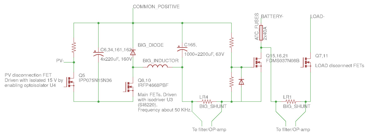
In an attempt to improve the charger I dived further into the design. I've got some requests to publish this, so here it is:High power path
The charger has a common positive rail for the PV, battery and load ports and it is asynchronous, not synchronous as first anticipated.See schematic:
Voltage regulators
There is a single buck regulator on the lower left part of the PCB, with the primary side of a transformer used as the inductor in the converter. It steps down to 5 V, and an LDO steps further down to 3.3 V. The fancy part of this design is that the transformer has three secondary sides. These secondaries are rectified/filtered to three independent/isolated 15 V outputs used for the following purposes:- PV disconnect FET drive
- Main FETs/isodriver (in buck converter)
- Fan and LOAD FETs
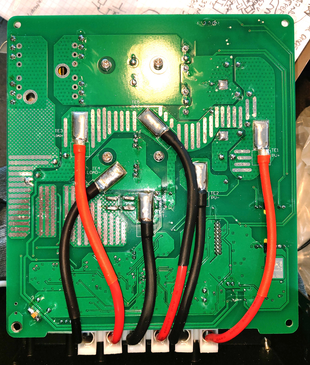
See overview of PCB front and rear side:
Voltage/current sensing
All voltage and current readings are passed through LM358 OP-amps. These have 1 mV max input offset voltage. When used as a shunt amplifier, this is a huge offset. On the unit I have the offset is unfortunately in the positive direction, which causes a negative output voltage with any measured current below 1.5 A and this cannot be measured by the ADC in the microcontroller. So the whole range from 0-1.5 A charging current is unavailable. There is no way to fix this in firmware. The "secret" menu in the Windows software for this charger allows a setting to compensate for gain errors, but this is a simplification which ignores the input offset and it is not possible to get good readings this way.Links
- Github repository for Python code used to request and parse readings
- An interesting forum thread in German, with someone connecting to the JTAG interface
- A PDF describing the RS-485 protocol, posted by jimbriam on the Github repository above