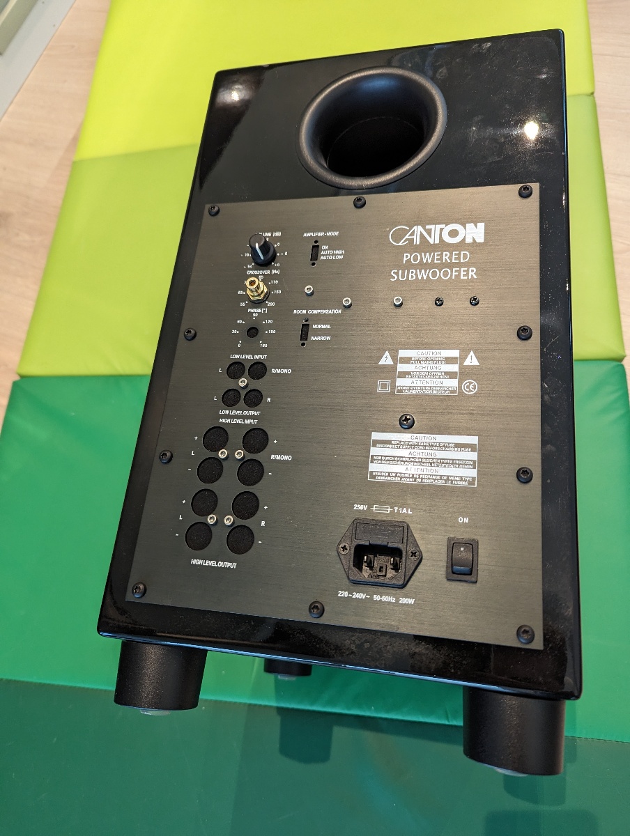
Canton AS 215 SC subwoofer repair
|
SummaryMany Canton subwoofers are prone to failing and unfortunately thrown in the bin. It's a shame, because mechanically, many of these subwoofers are quite good. More specifically, what is almost always failing is the standby circuit that turns on the amplifier if a signal is present. Also, if you manage to turn it on, input levels might be very low or distorted. The fix I'm suggesting requires no troubleshooting on your side, and what we're doing is basically removing the parts of the subwoofer that is prone to failing, and making the amplifier operate without those parts installed. |
If you're only interested in the repair steps, scroll down to "Solution/repair"
Tech specs
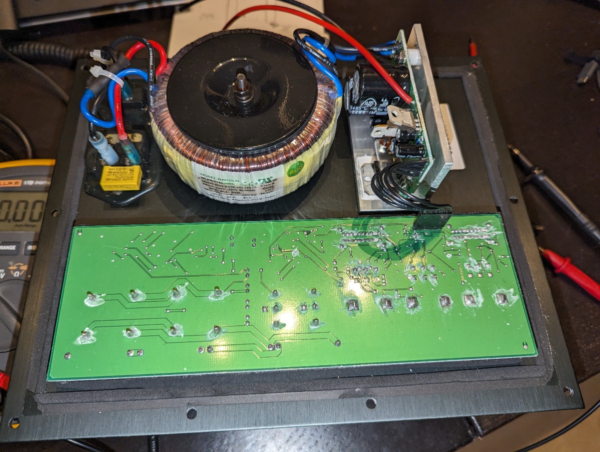
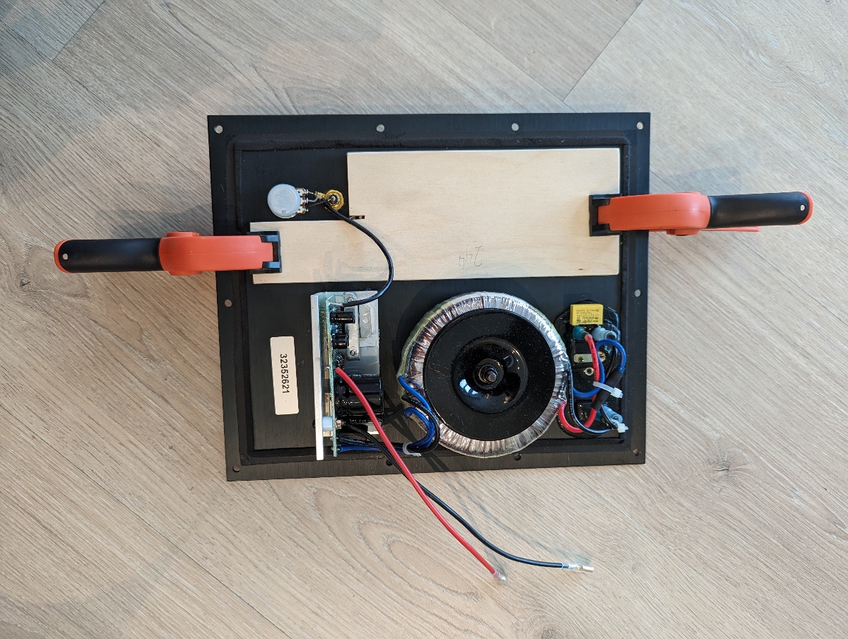
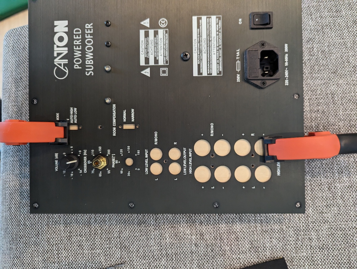
The subwoofer has three main parts:- A 2x30 V transformer (approx. +/- 42 VDC rectified)
- An amplifier (top right) built around a TDA7294S amplifier module, and also holding linear regulators to provide +/- 12 V for the input/filter board
- Input/filter board (bottom) which is powered all the time to provide an auto-on feature in prescense of a signal. It also provide a crossover filter and low/high level inputs.
The 6-pin connector going into the input/filter board has the following pinout on the amplifier module side: (Pin 1 is closest to the edge of the board.)
- 1: Audio in
- 2: Audio GND
- 3: Standby signal
- 4: 0 V
- 5: -12 V
- 6: +12 V
The input board is also prone to failing, and mine didn't work when providing clean +/- 12 V. As I read about many issues with this board, I didn't even bother troubleshooting it, and decided to skip the entire board.
Removing the board means we lose some things:
- The filter: Who doesn't have a receiver with a crossover filter built in anyways?
- The high level speaker inputs: Never used them...
- The auto-on feature: I prefer my subwoofer to turn on immediately when I power on my speaker system, so this didn't bother me. However, without this feature we need a different way of getting the amplifier to turn on.
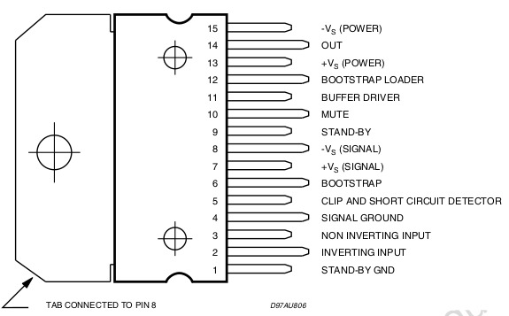
The TDA7294S pin 9 is controlled by the auto-on feature. We don't want to pull this signal right to V+, as we want a delay from when power is applied until the output is enabled. This delay makes sure bias voltages are stabilized before audio is enabled so we don't get a loud pop when powering on the subwoofer.
Luckily, there is already footprints on the board to enable this circuitry. Seems like they planned for this board to be used without the auto-on feature.
I wanted the startup delay to be as long as possible, so by soldering a 22.1k resistor in footprint R57, the voltage on the standby pin would slowly rise to about 7 V as the (already populated) capacitor is charging, while still having enough margin above the rising threshold of 3.5 V on the TDA7294S standby pin.
Solution/repair
Modify the amplifier
- Remove the 7812 and 7912 regulators
- Desolder the 6 black wires from the amplifier module
- Solder a 22.1 kohm (anything from 4.7k to 22.1k will do) resistor in footprint R57
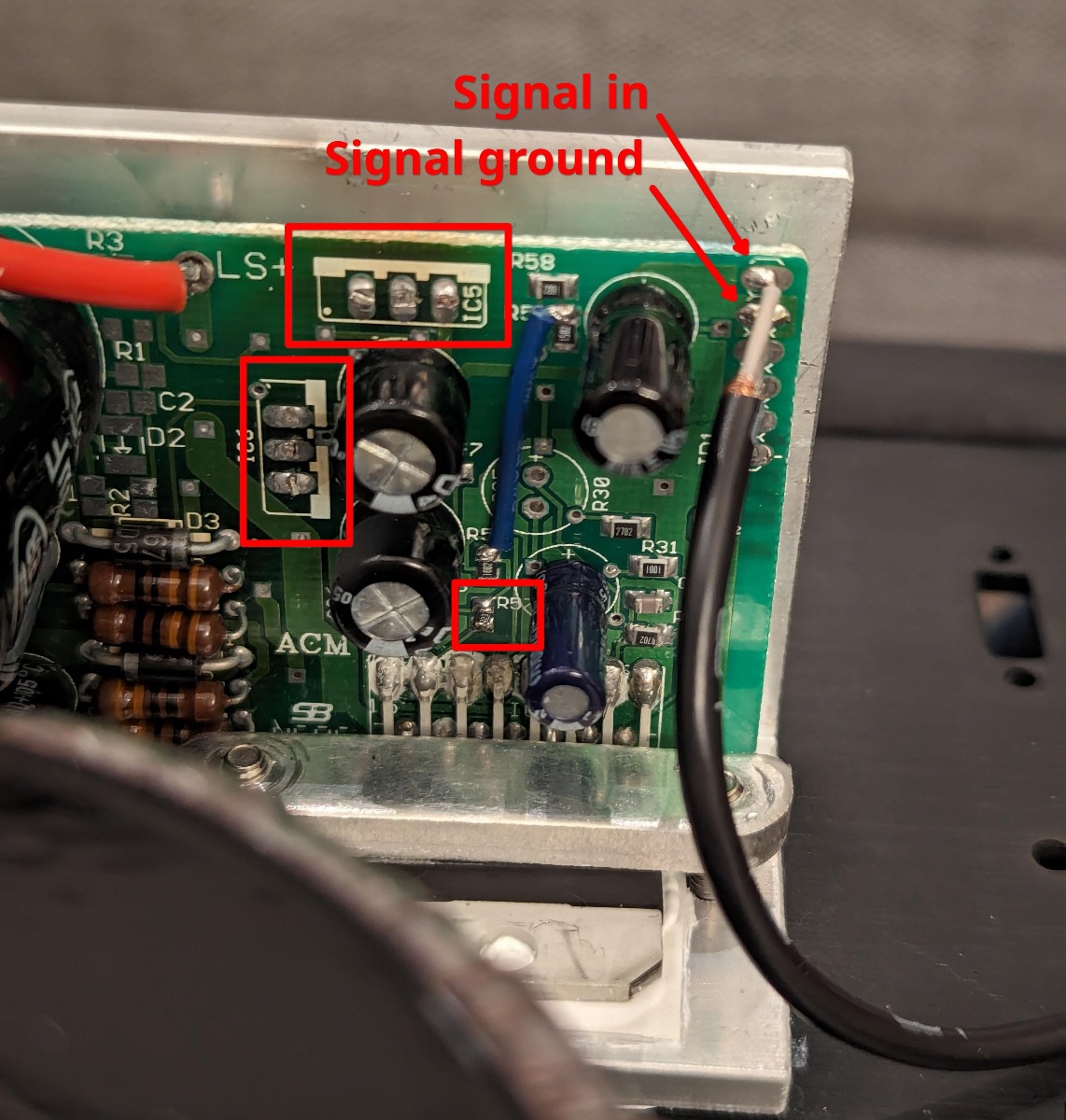
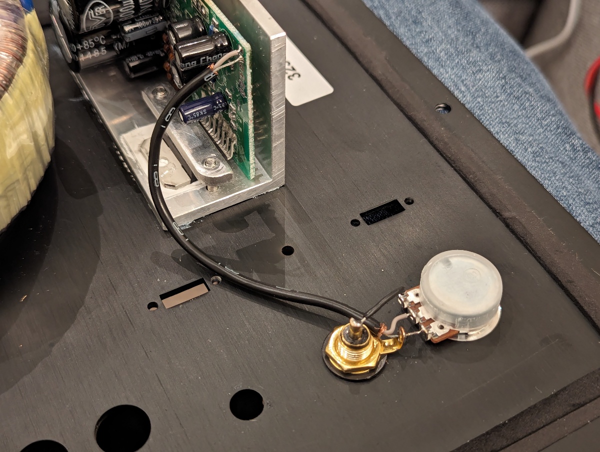
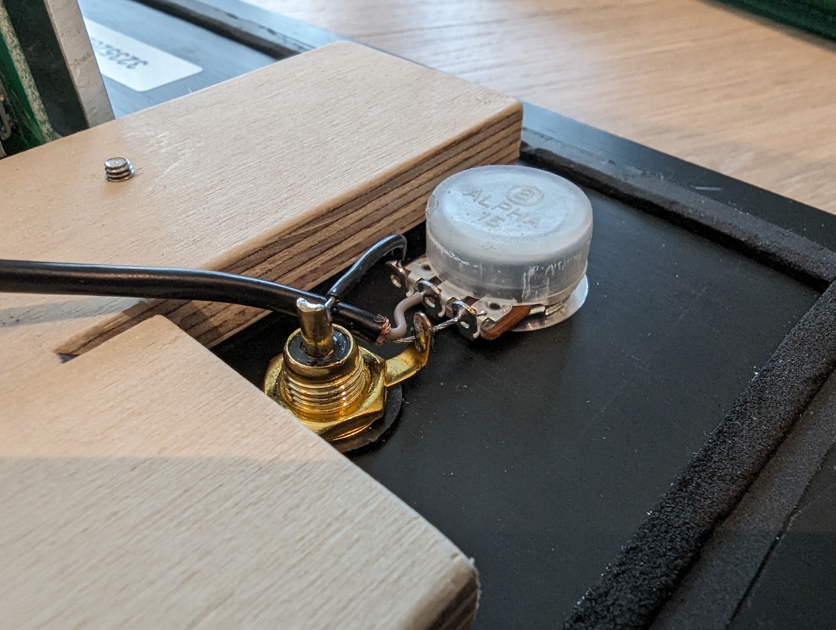
- Mount an RCA connector and 10 K pot
- Feed the signal from the RCA connector to the potmeter, and then to the two outer pads on the amplifier board, as shown in the images below.
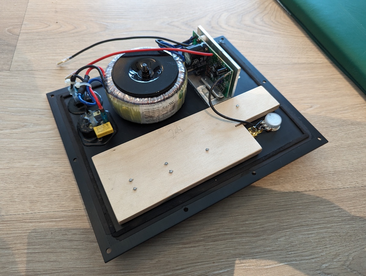
Remove the input/crossover filter board and make the amplifier airtight
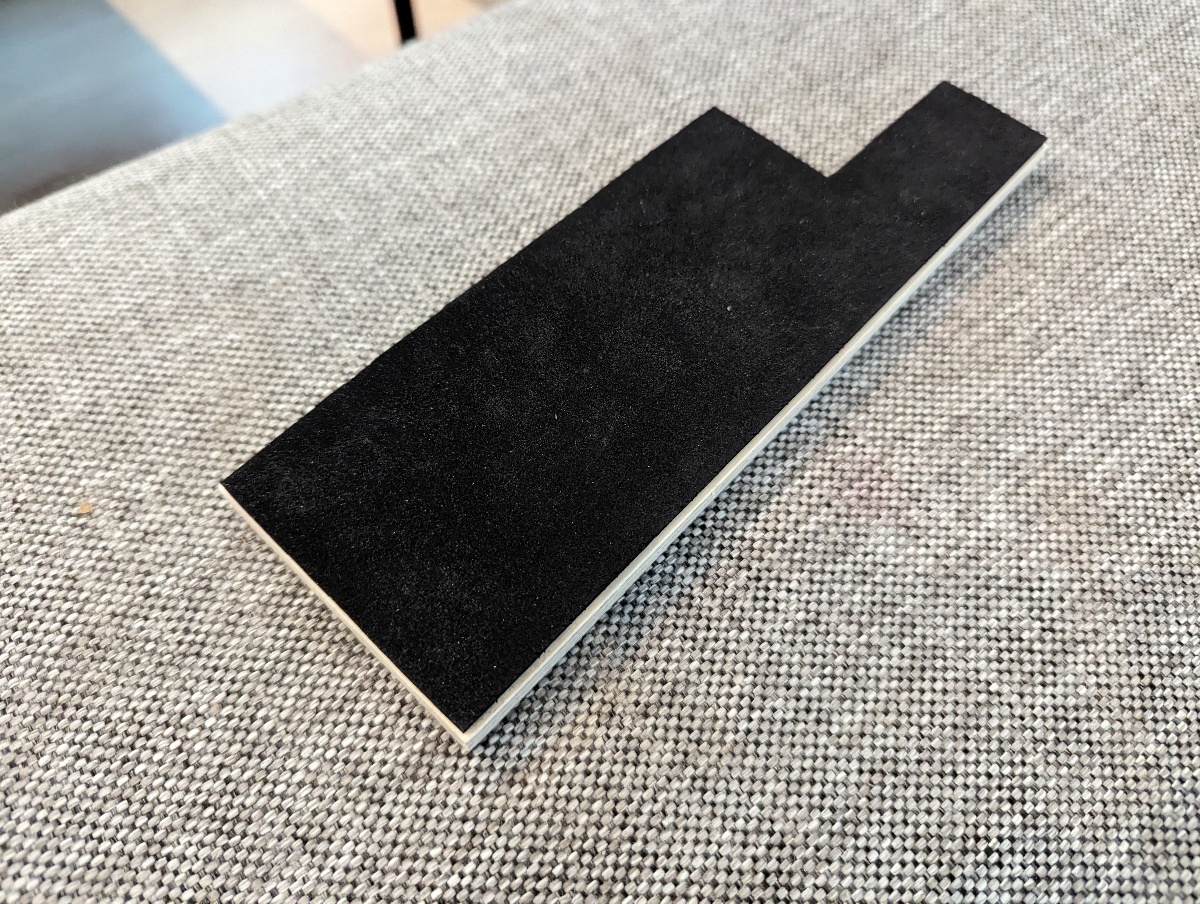
I used a sheet of plywood with a neoprene gasket pushed against the aluminium back plate to seal it. There are probably many other ways this could be done.- Remove the input/crossover filter board
- Cut a sheet of plywood to size and clamp it to the amplifier
- Drill 2.5 mm holes in the plywood aligned with the existing mounting holes
- Cover the plywood sheet with a gasket on the inside. I used an adhesive sheet of neoprene.
- Tap the 2.5 mm holes with an M3 tap and tighten appropriately so the gasket is pushed against the aluminium.
- Assemble the amplifier.