Owl VHF - a versatile digital radio transceiver
Introduction
The Owl VHF project was primarily started as I wanted a small packet radio transceiver to test AIS, AX.25/APRS and higher speed amateur radio modes. Current available amateur radio solutions were too big and limited to AX.25. This motivated me to start working on a new design. The design is, among other, chosen as the primary radio in the EOS2 project, and proposed as a telemetry radio solution in the student satellite program NUTS at NTNU as well.Hardware design
First of all, a very small single chip transceiver was chosen as the core component. In recent years these transceivers has gone through a jump in performance, and they are no longer limited to low performance garage door openers, alarms etc. Digitalizing the IF using high dynamic range A/D-converters allows digital IF-mixing and digital channel filtering, in turn shrinking the size significantly compared to larger analog multi-IC solutions.Secondly, it was chosen to use a modern 32-bit PIC microcontroller to do software (de)modulation. Due to the relatively low data rate and narrow band applications, the performance was found to be more than sufficient.
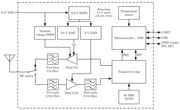
To further improve performance of the transceiver chip, a front end with a 1 dB NF LNA was made - much better than the internal LNA. A low insertion loss filter was placed before the main LNA to improve out of band blocking performance, and another filter with much steeper roll-off characterstics was placed after the LNA to even better eliminate out of band interference.
The main PA is based on a Mitsubishi PA module characterized by sweeping Vdd, Vgg and Pin to find optimal biasing for a given output power. Combined with a highly efficient variable switch mode power supply for PA drain supply, this allows very good efficiency over a large span of output power settings.
A block schematic is revealed below.
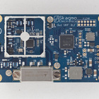
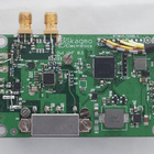
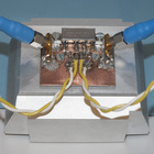
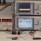
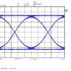
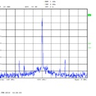
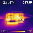
The hardware has gone through several iterations of designing, testing and revising, and RF-performance, current consumption, thermal characteristics etc. has been evaluated for every iteration. The images below shows, among other stuff, the first PCB revision. This was mainly used to do isolated tests of the subsystems and to verify footprints.
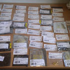
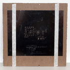
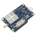
The current revision parts, stencil and PCB is shown below. Components were placed by hand and reflow soldered in a convection oven.
