
Analog telephone exchange
|
An introduction to my MCU based fully featured analog telephone exchange, how I mounted it in my home lab powered with batteries for months of use "off-grid", and how I set up a tiny telephone network. |
Motivation
A few years ago, an analog phone exchange would probably be one of the last things I thought I would build. However, last year I decided to dig into the old POTS (Plain Old Telephone Service) standard, search Finn (the norwegian equivalent to Craigslist) for old phones and start designing a phone exchange. Why on earth would I do this?- I love working with old communication protocols and standards. Imagine reading a well defined standard from a yellow stained paper written in the 1970's, while you are writing firmware for a modern MCU.
- My daughter is really into toy telephones, so what wouldn't be cooler than mounting a proper phone in her room and enabling her to call us and her grand parents?
- We have an unused CAT6 cable between our house and my parents house, as well as a lot of CAT6 wiring in our (pretty new) house, so all the cables are already in place.
Here's a demo of the finished phone exchange:
Hardware architecture
The first questions that came to my mind was how old school this was going to be:- Would I use relays or semiconductors for the switching matrix? I do love the sound of clicking relays, but I ended up with solid state analog MUXes which saves a lot of PCB area.
- Would I use dedicated analog circuits like the old MT8870 DTMF decoder? No, I decided this was a good opportunity to do some DSP in firmware and also save PCB area by using the ADC in the MCU and write the DTMF decoder in firmware.
In other words, I've made some modern twists to an otherwise old design.
Another important design decision was to have line interfaces as separate PCBs, both to be able to use different kinds of physical interfaces (such as wired POTS, wireless etc.), and because the mainboard otherwise would be very large and full of similar circuitry. If I were to make another revision of the main board, I could simply plug the interface boards into the new main board.
I also use 100 mil pitch edge card connectors because they give me a warm fuzzy retro feeling ;) (And of course it saves me the effort of not having to solder a connector.)
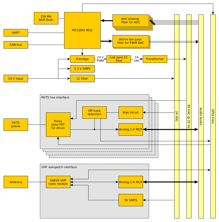
This is how the architecture ended up:
Main board
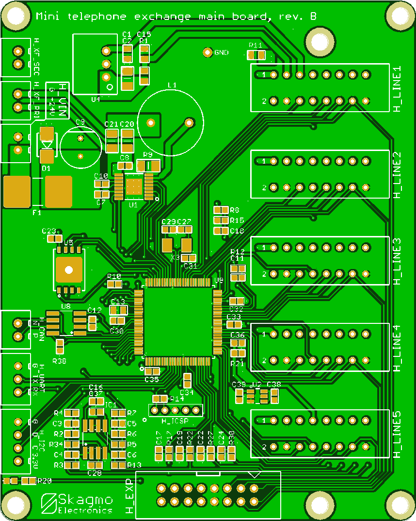 The heart of the main board is a PIC32MX575F512H microcontroller.
This does really all the heavy lifting.
The heart of the main board is a PIC32MX575F512H microcontroller.
This does really all the heavy lifting.
- 4 ADCs are connected to the four audio buses to be able to decode DTMF in firmware and record audio (voice mail etc.)
- 2 PWM modules are filtered with a third order active low pass filter to work as DACs, feeding audio bus 1 and 2 to provide ring tone, play back audio etc.
- It controls an H-bridge with a look-up table to create a perfect 25 Hz sine ringer voltage
- UART and CAN bus is exposed on connectors. UART is used to log events and debug, CAN bus is used to connect the phone exchange to my CAN based home automation system. It would be able to trigger events when dialing certain numbers, make phones ring from Home Assistant etc.
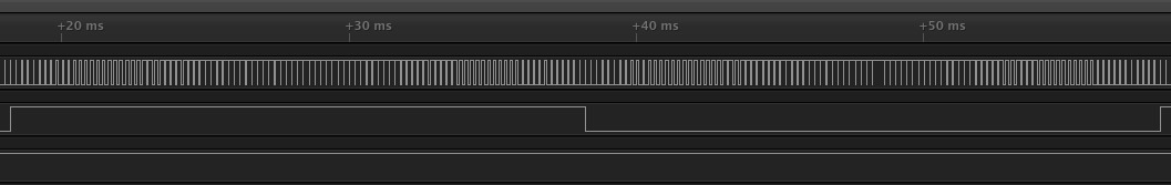
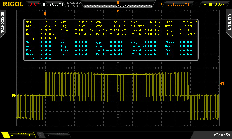
- Generate the PWM and direction signal from the MCU, using a sine LUT and a PWM peripheral
- Output from H-bridge
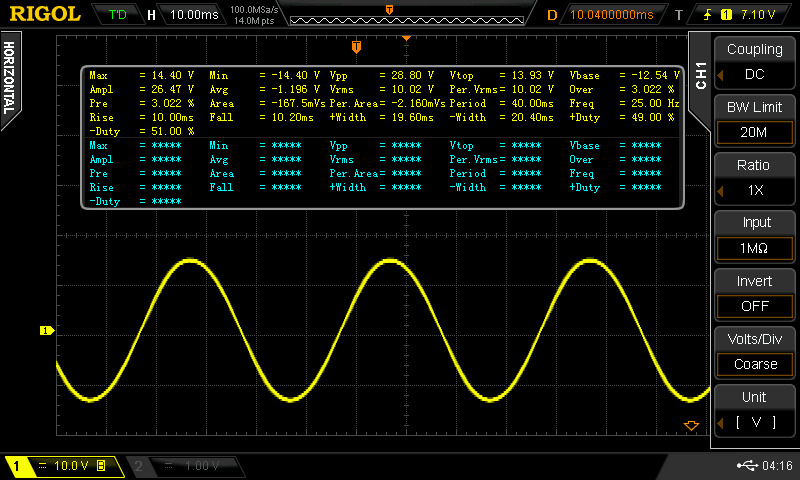
- LC-filtered signal (low voltage 25 Hz sine)
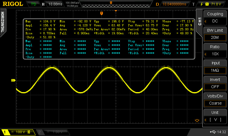
- Output from transformer (high voltage sine)
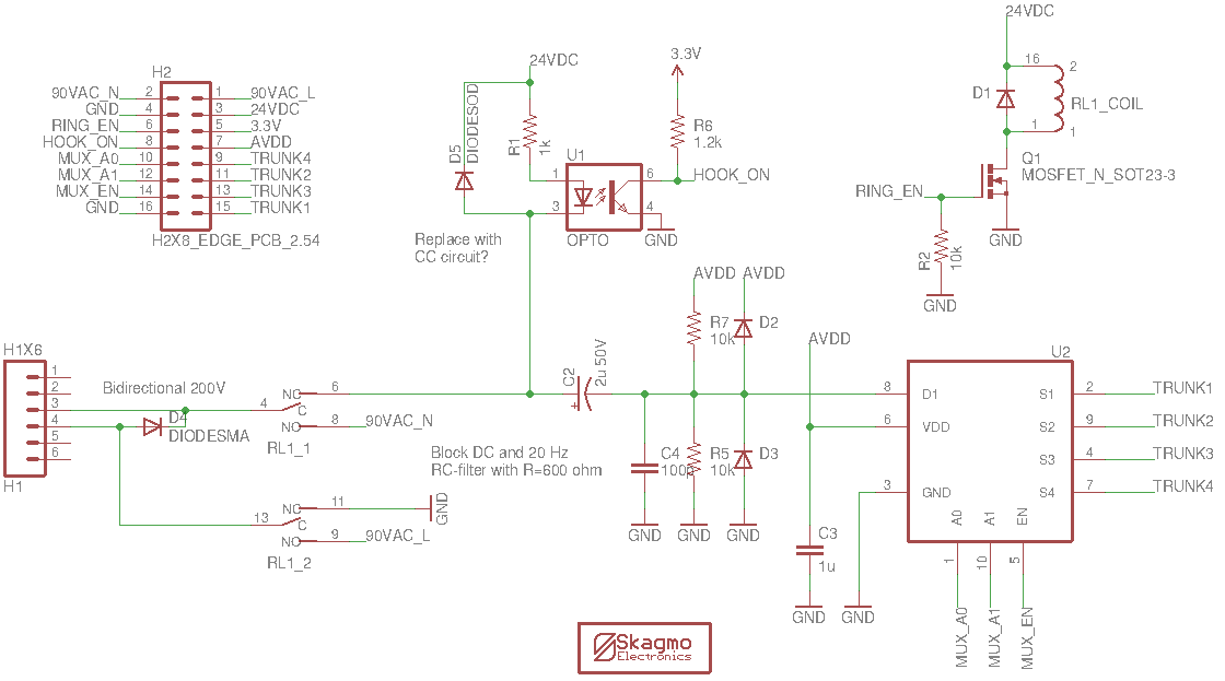
POTS line interface board
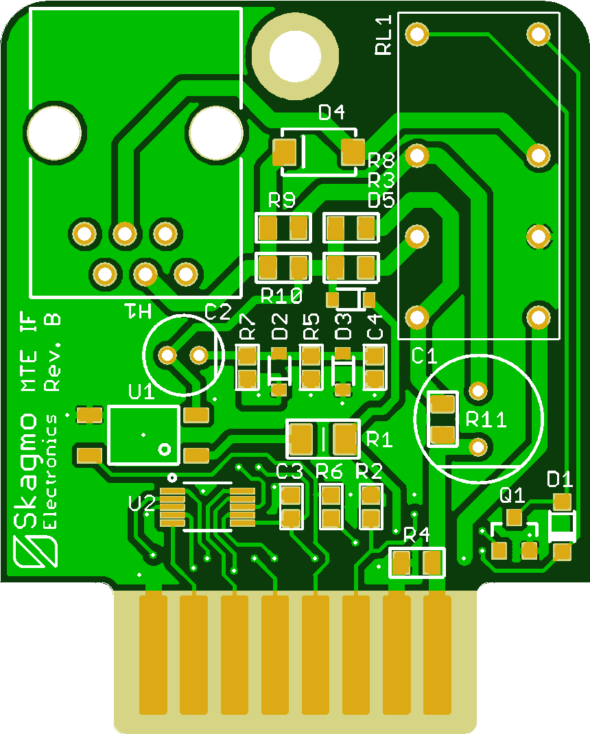 The line interface board holds all the circuitry required to interface a single POTS phone to the main board:
- RJ11 connector
- DPDT relay to toggle between 24 VDC bias + audio signal OR the 90 VAC ringer voltage
- Optocoupler circuit to detect the off-hook current
- Analog MUX to connect the line to one of the four audio buses
- Protection circuitry
I actually implemented both methods, but ended up using the method with no bias during ringing for it's simplicity.
However, there is one caveat. To detect when a phone goes off-hook, you detect an increase in bias current. If the phone rings and there is no bias voltage, you couldn't detect that the phone is off hook. The way I solved this was to monitor the H-bridge current for the ringer circuit using an ADC on the MCU. If the ringer current rises above a threshold, the phone would be considered off hook and the ringer stops immediately.
Autopatch board
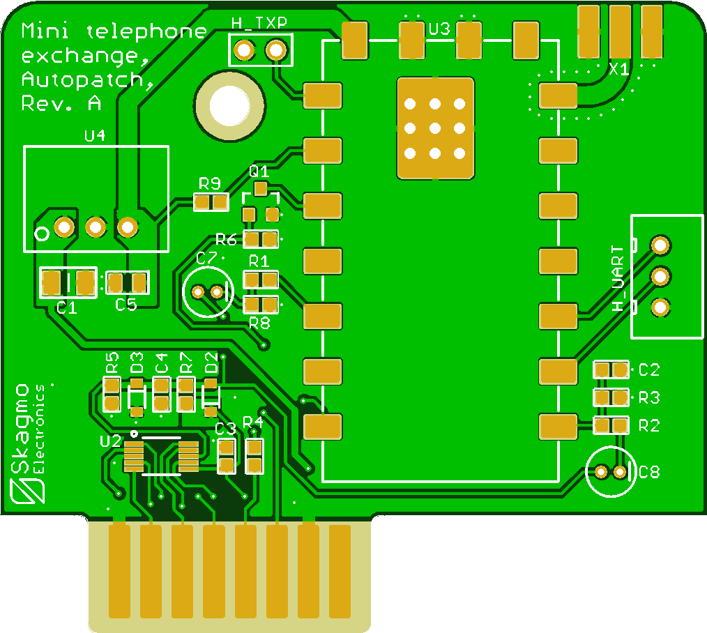 The autopatch board enables dialing into the phone exchange from a handheld radio, or answering incoming calls on the handheld radio.
I decided to use a simple FM "walkie talkie" transceiver module for this purpose.
I first tried SA818, but turned out to be completely unsuitable due to a large TX delay. It took almost a full second from enabling the PTT line until the TX audio became undistorted. Sounds like a coupling capacitor in the AF path charging up to a certain bias level very slowly.
Second try was the RDA1846S module (link here). This is a lot better and has only milliseconds of delay before TX is at full power and undistorted.
Firmware architeture
The firmware was written in bare metal C, although in an "object oriented way" with a context/handle for each of the phone lines. DTMF decoding is done with the Goertzel algorithm, matched for each of the 8 different frequencies used for DTMF. Four instances runs in parallell to be able to decode DTMF continously on all four audio buses. There is a big state machine handling all phone states, callbacks for events like off-hook, new DTMF data etc.Assembling it all togheter
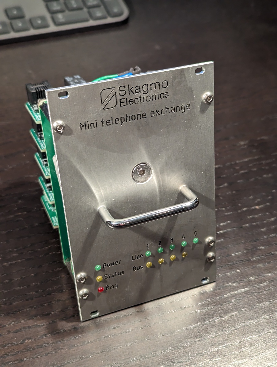
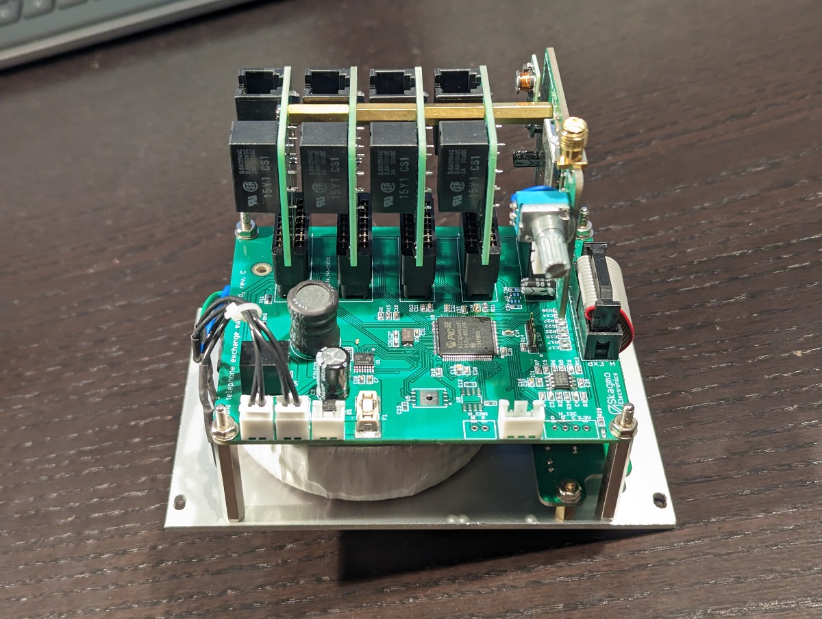
Here is the whole assembly with a CNC routed aluminium front plate for subrack mounting, toroidal transformer, main board and all interface boards.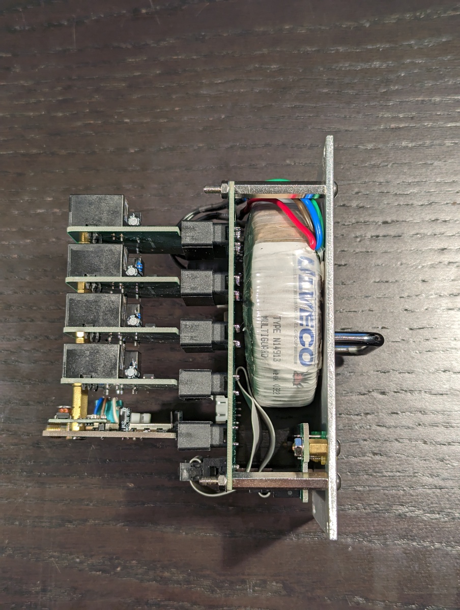
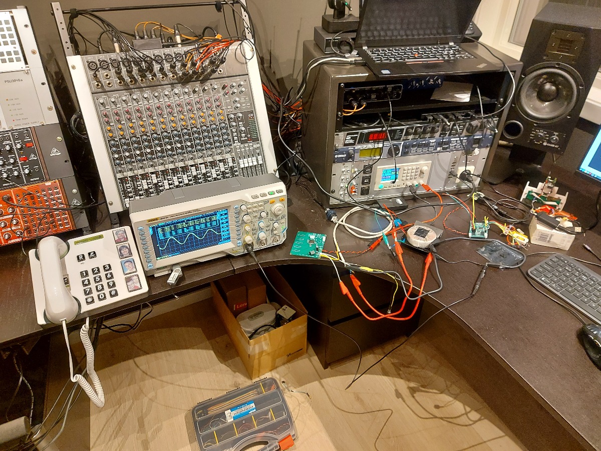
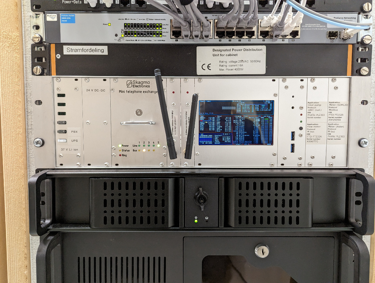
Permanent mounting
I mounted the phone exchange in my "home lab" rack together with my networking and home automation equipment.It is powered from a 2.5 kWh 37 V (10S) battery pack made from Nissan Leaf battery modules. This powers my main UPS, but rather than using the UPS to go from 37 VDC -> 230 VAC -> 24 VDC I use a DC/DC converter to go directly to 24 VDC. This means that in a power outage I'm able to use the phone exchange for months after the UPS has turned off. Not that I would ever need it ;)


Setting up a private phone network
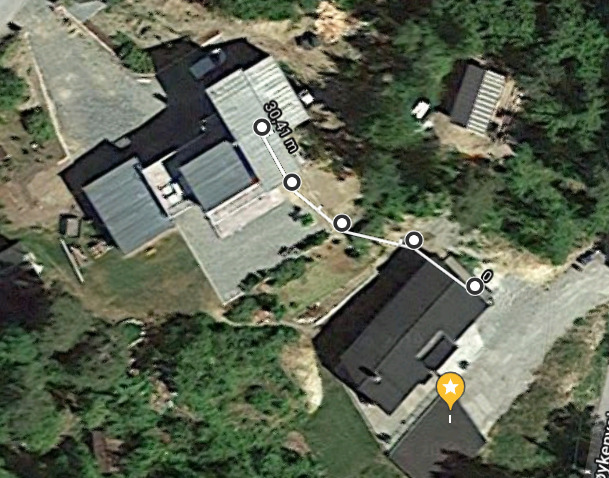
I mounted a Diamond X-30 antenna on the roof for the autopatch, which will give me plenty of range when I'm cross country skiing or hiking in a nearby mountain and need to dial home for some reason. My daughters room was upgraded with a phone mounted next to the bed, and the last image shows the underground cable from our house to my parents house.

It's been giving us and our daughter a lot of fun, and has also proved to be really useful.