The over-engineered kids car
|
I bought an electric kids car for my daughter and stuffed it with electronics to make a music player system, better motor control, an aluminium dashboard and more. |
Introduction
Original car
Initially I wanted to make the whole car from scratch, but I had to limit the scope of this project and focus on what I enjoy the most; the electronics. So I bought a used off-the-shelf kids car with a dead battery to use as a starting point.The original architecture was super simple and had no electronics.
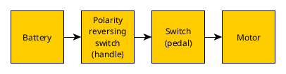

New hardware architecture
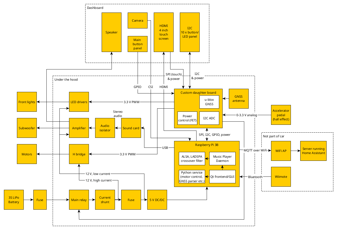
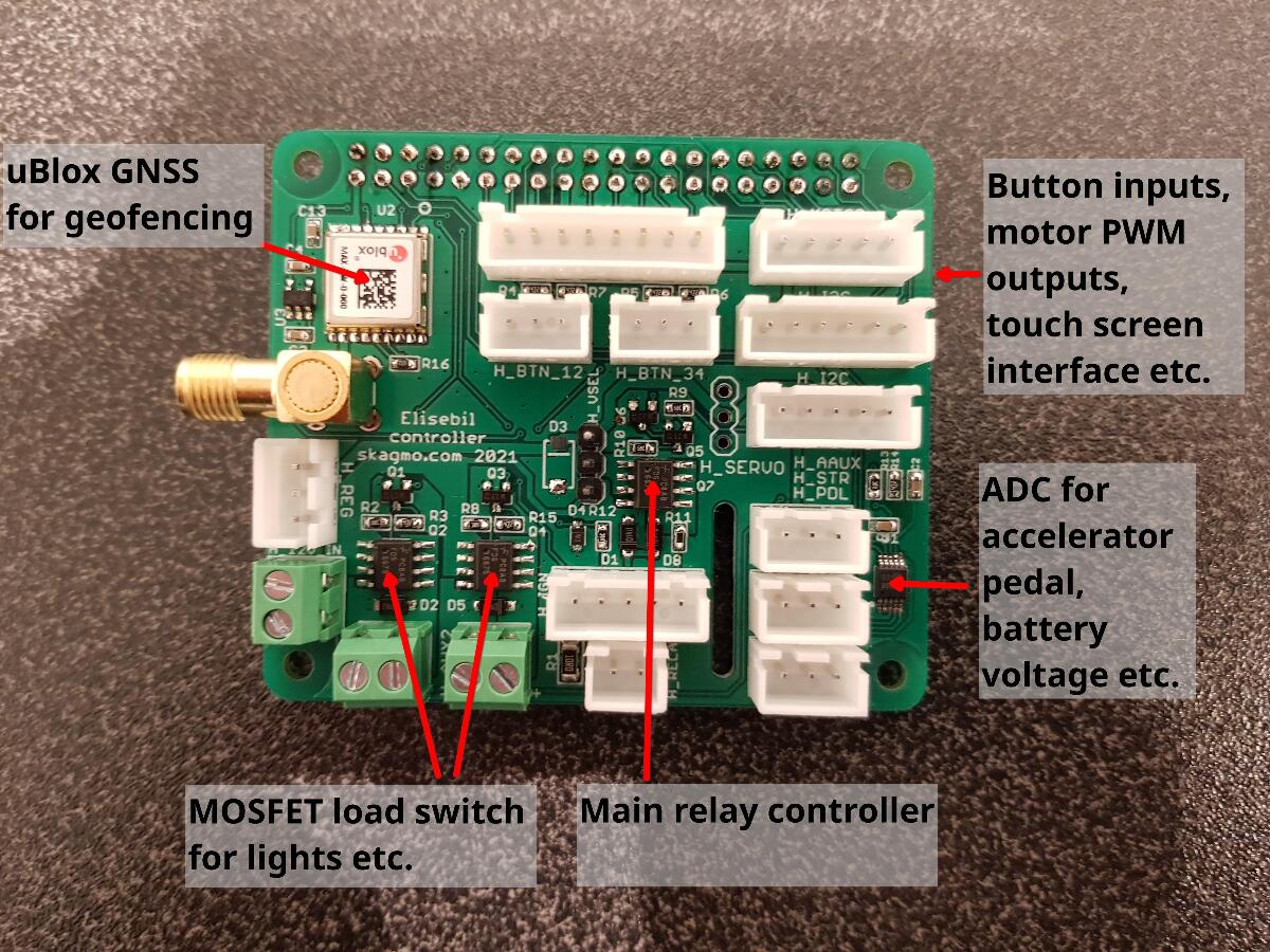
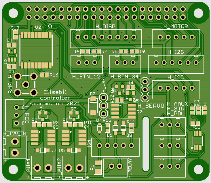
The block schematic explains what I've put into the car, but some details need to be elaborated:
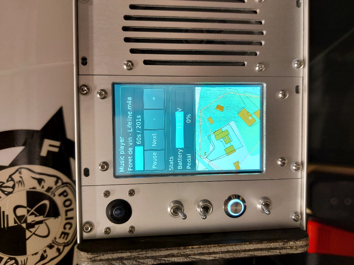
- The GPS/GNSS was originally meant for geofencing. You might notice the small map section on the touchscreen. The dashed line is a geofence, and driving outside this line would originally stop the motors. After my daughter had been driving for a few minutes, I quickly realized it was a little naive to keep her inside that small confined geofence, so it was disabled quite soon ;)
- The MQTT connection is used to be able to open the garage port from a button on the dash board.
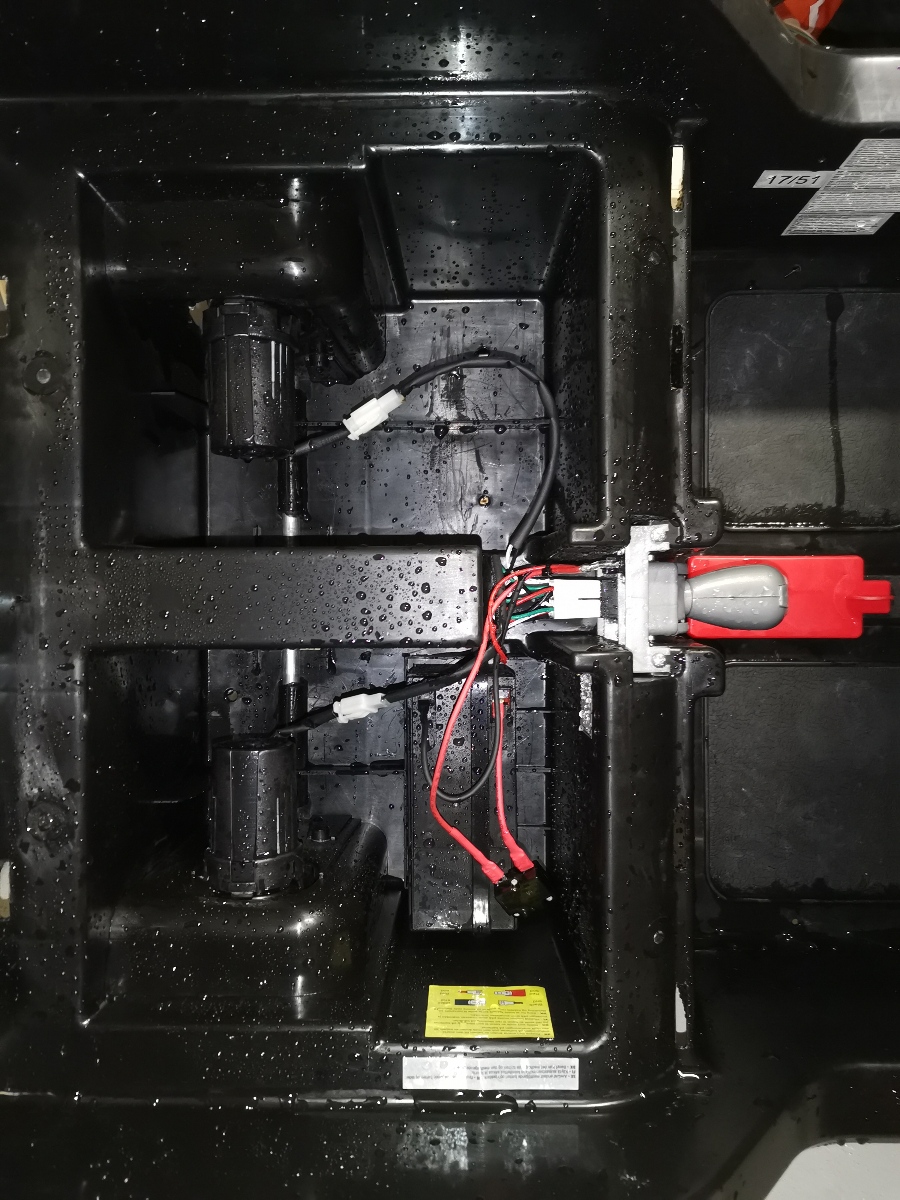
- The main relay is engaged directly with a button on the dash board. As soon as the RPi starts booting, it will keep the relay engaged. When the battery voltage goes below the lower voltage limit, the Raspberry Pi will shut down and finally cut power to the relay so the battery is completely disconnected to prevent any damage.
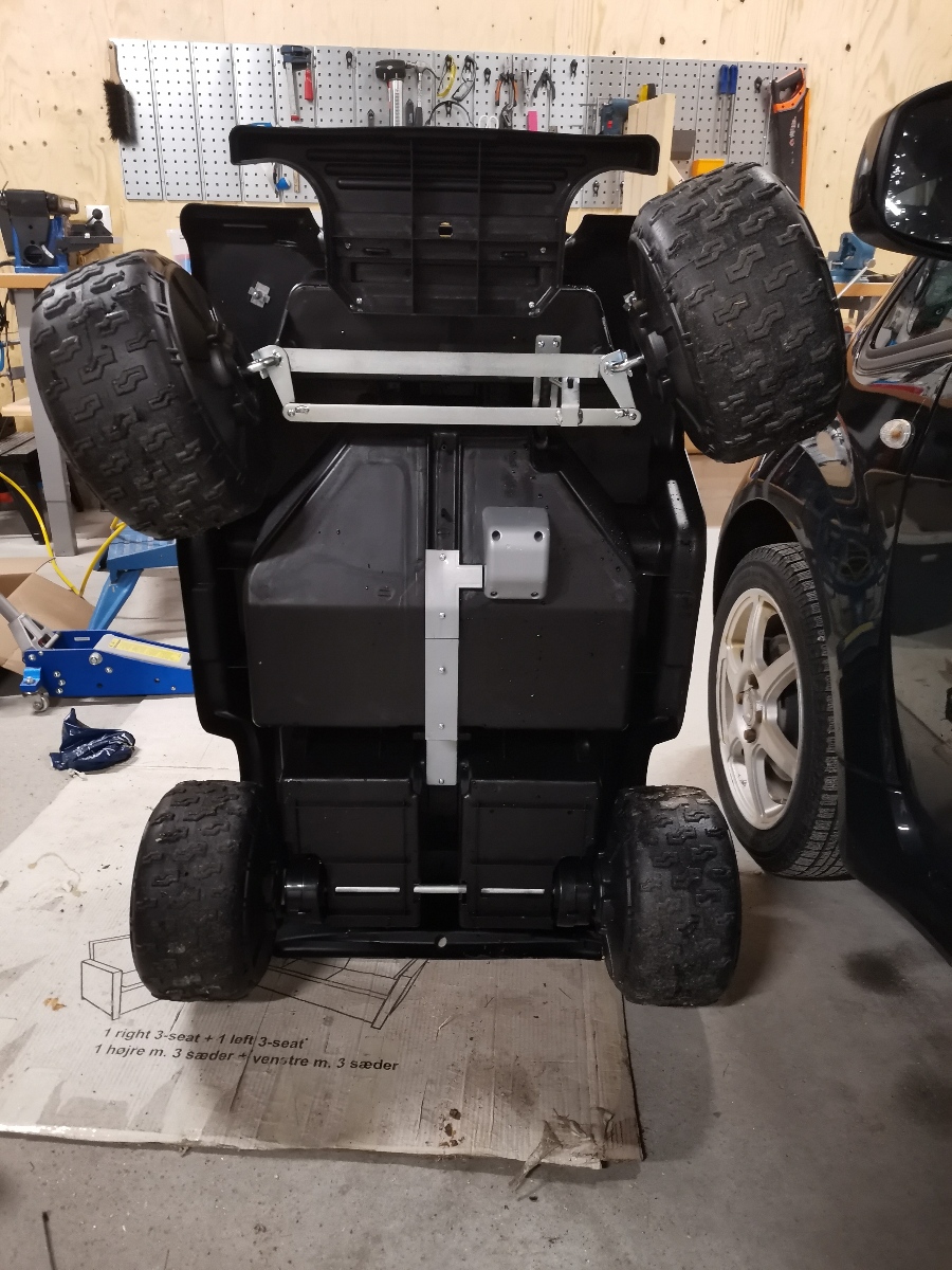
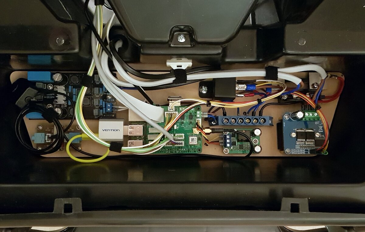
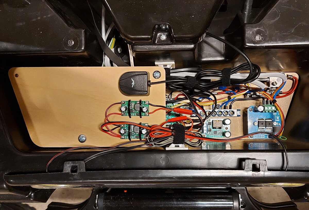
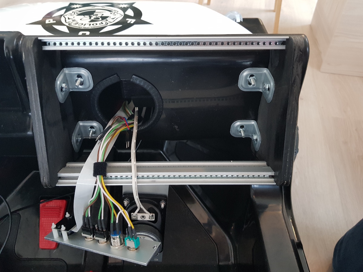
Under the hood
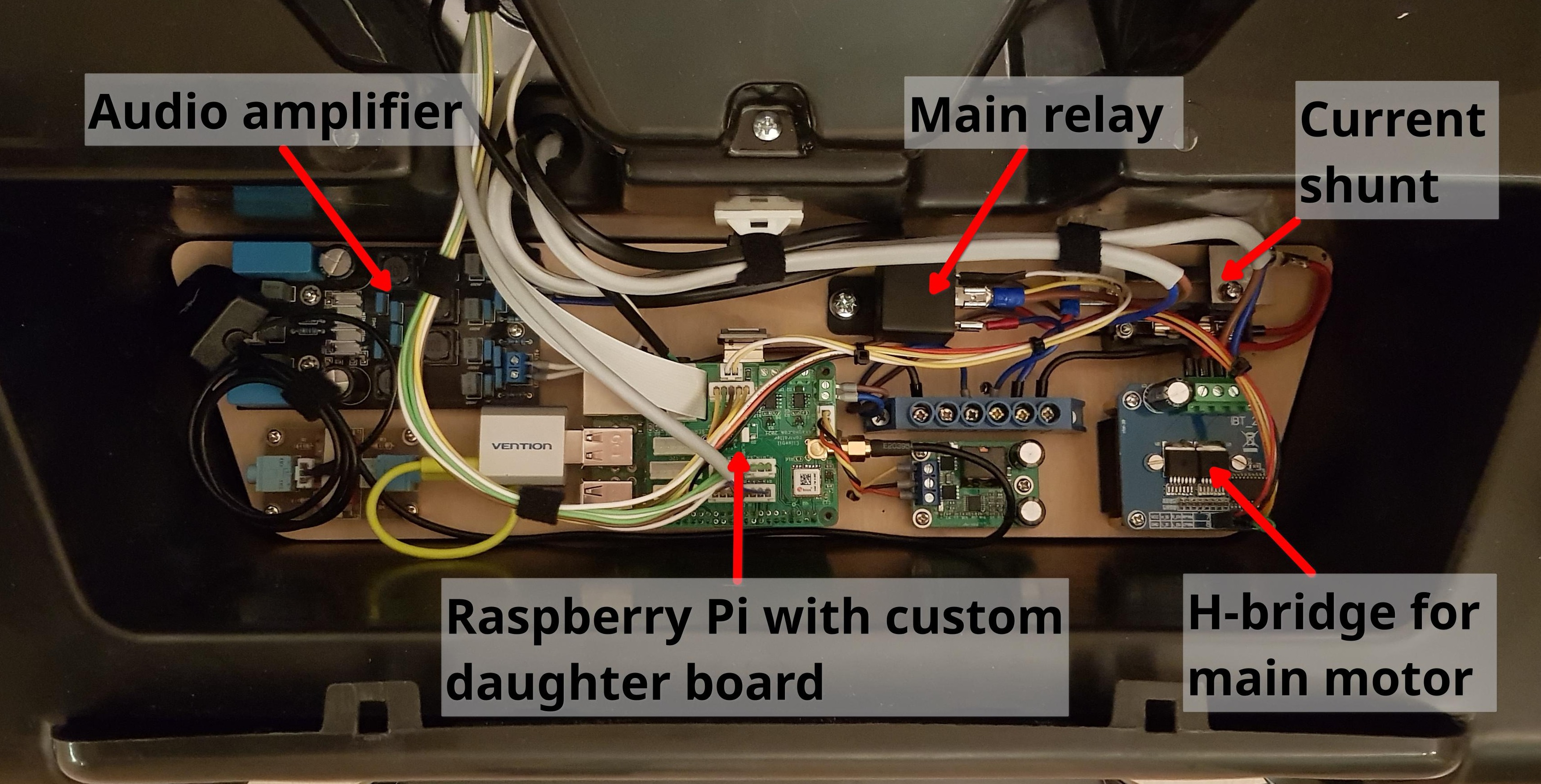
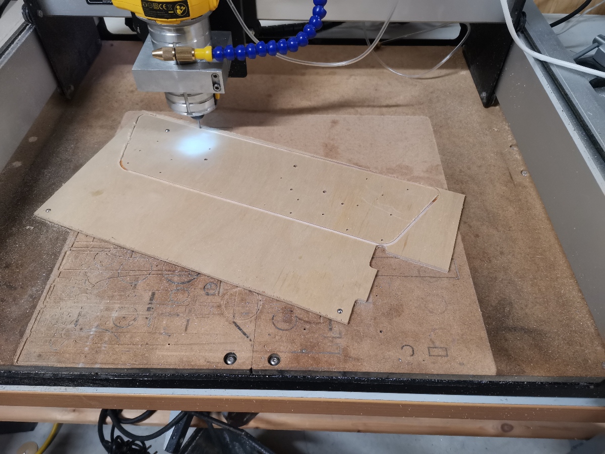
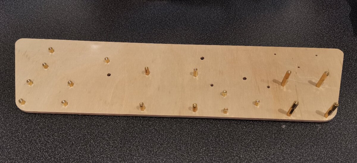
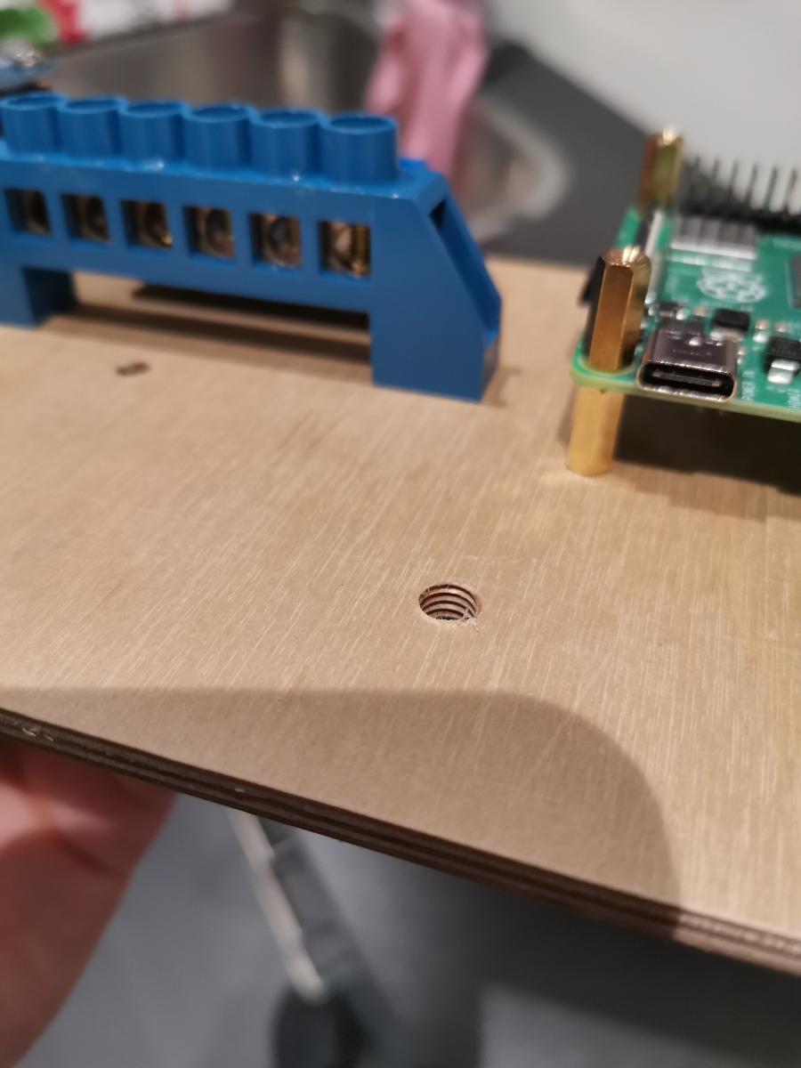
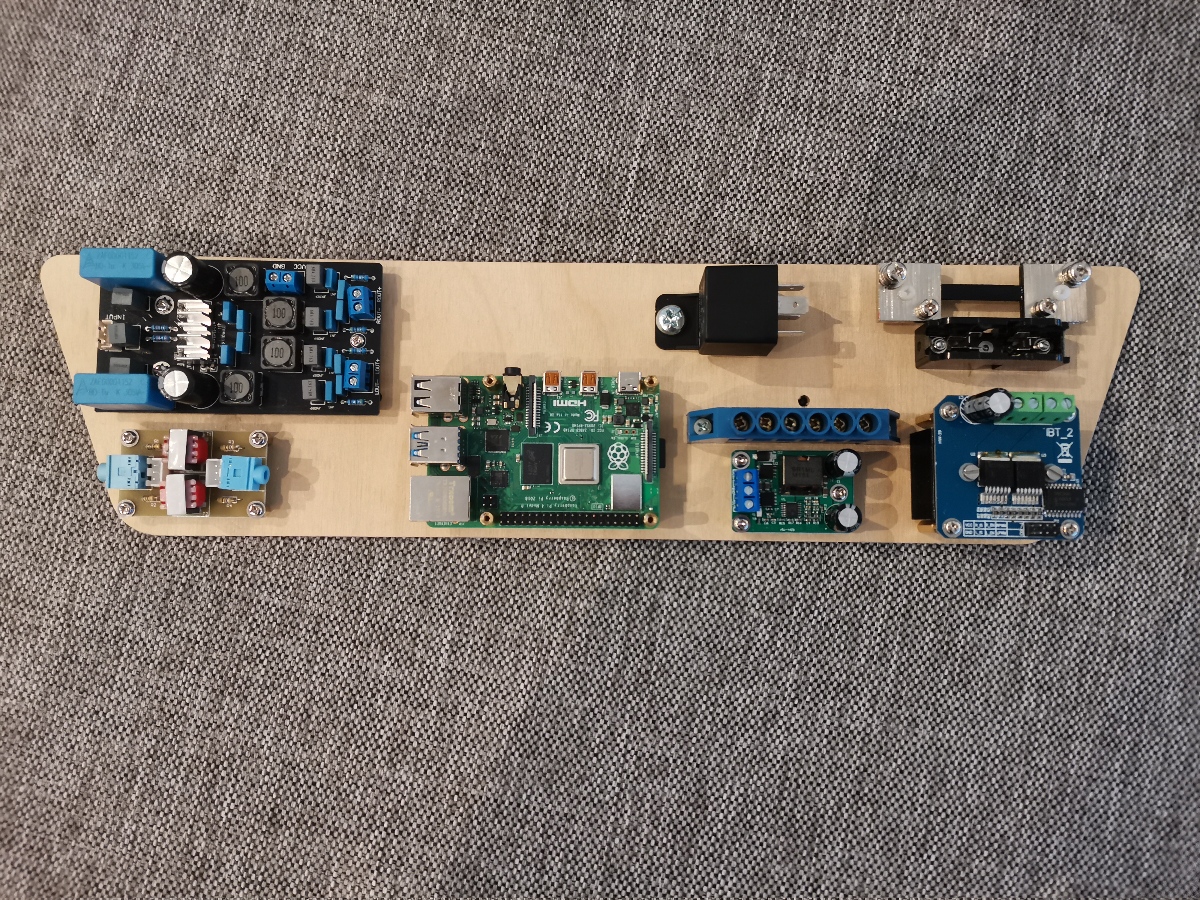
I routed a mounting plate from plywood, and mounted all the parts on brass standoffs.
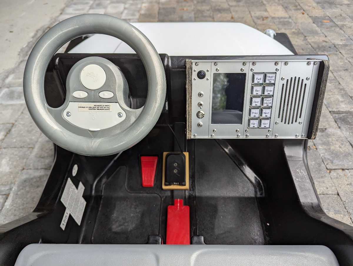
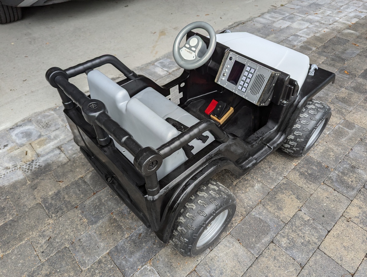
Dashboard
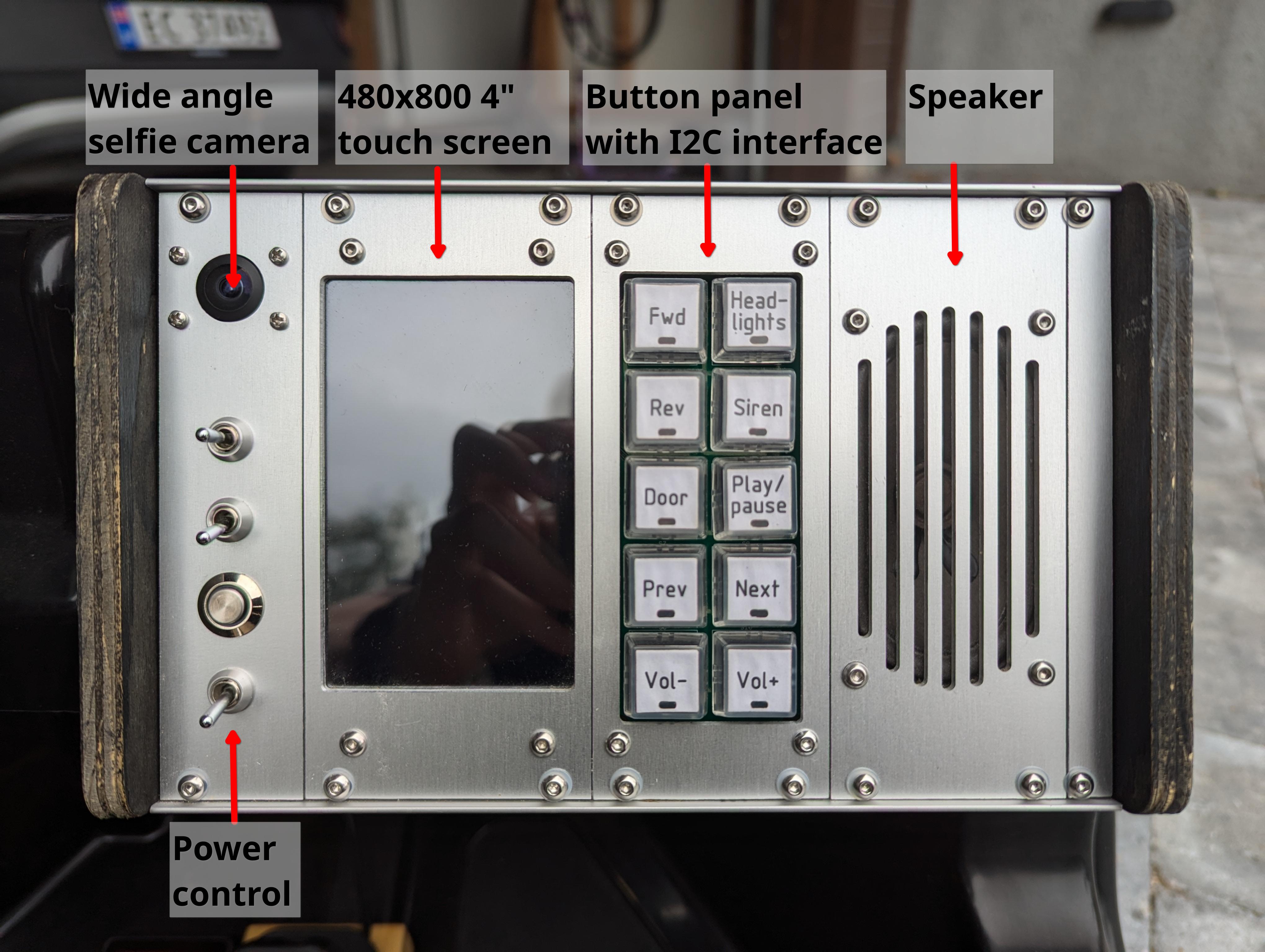
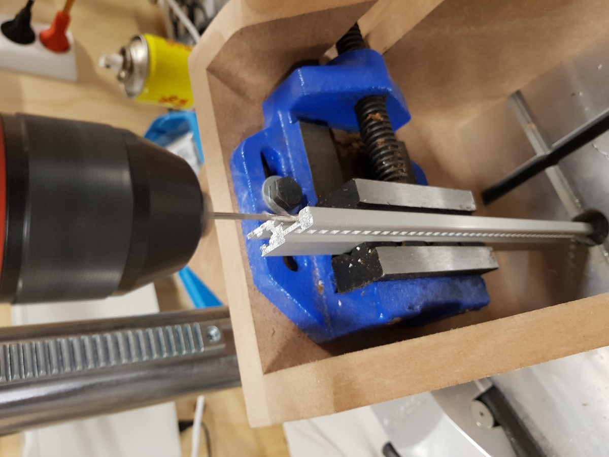
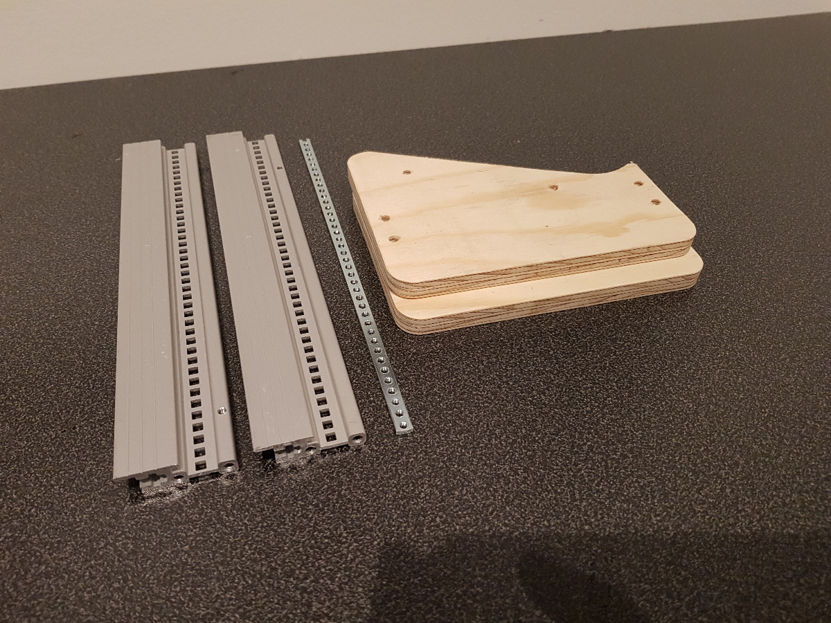
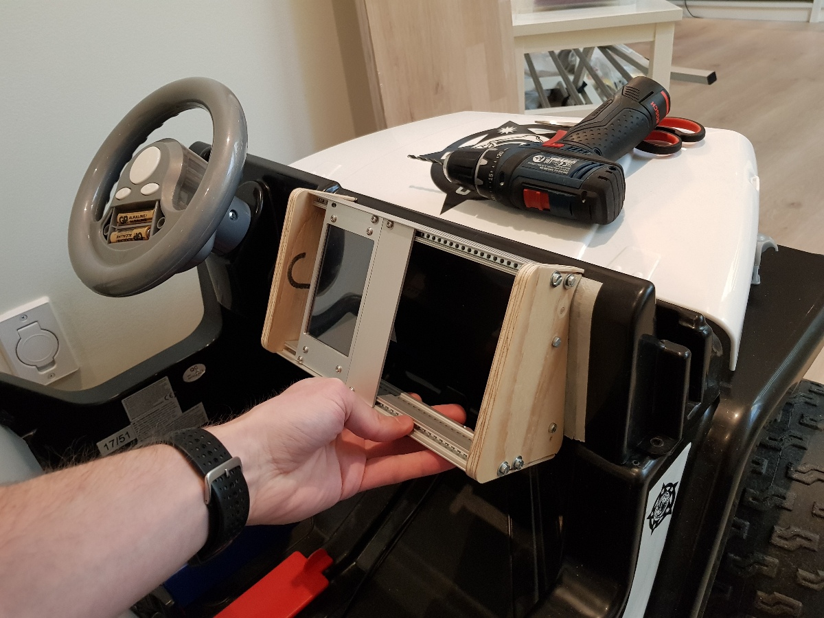
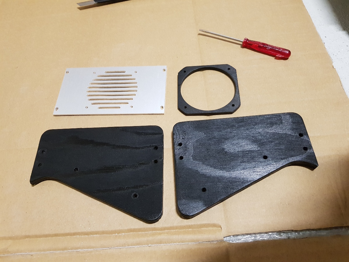
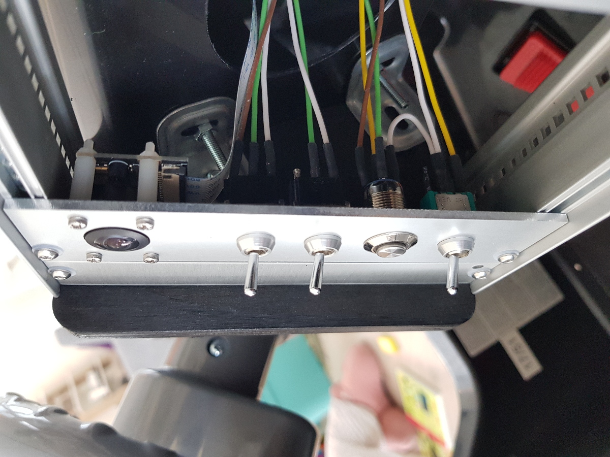
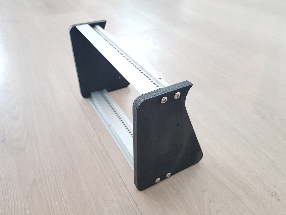
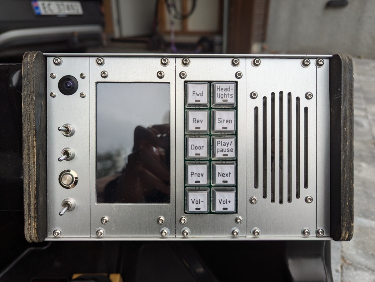
The dashboard was the main effort in this project. It's based off the 3U subrack form factor which I use in so many of my other projects. The sides are made from plywood, and the panels are all machined from 2.5 mm aluminium sheets. There are four modules. Starting from the left:
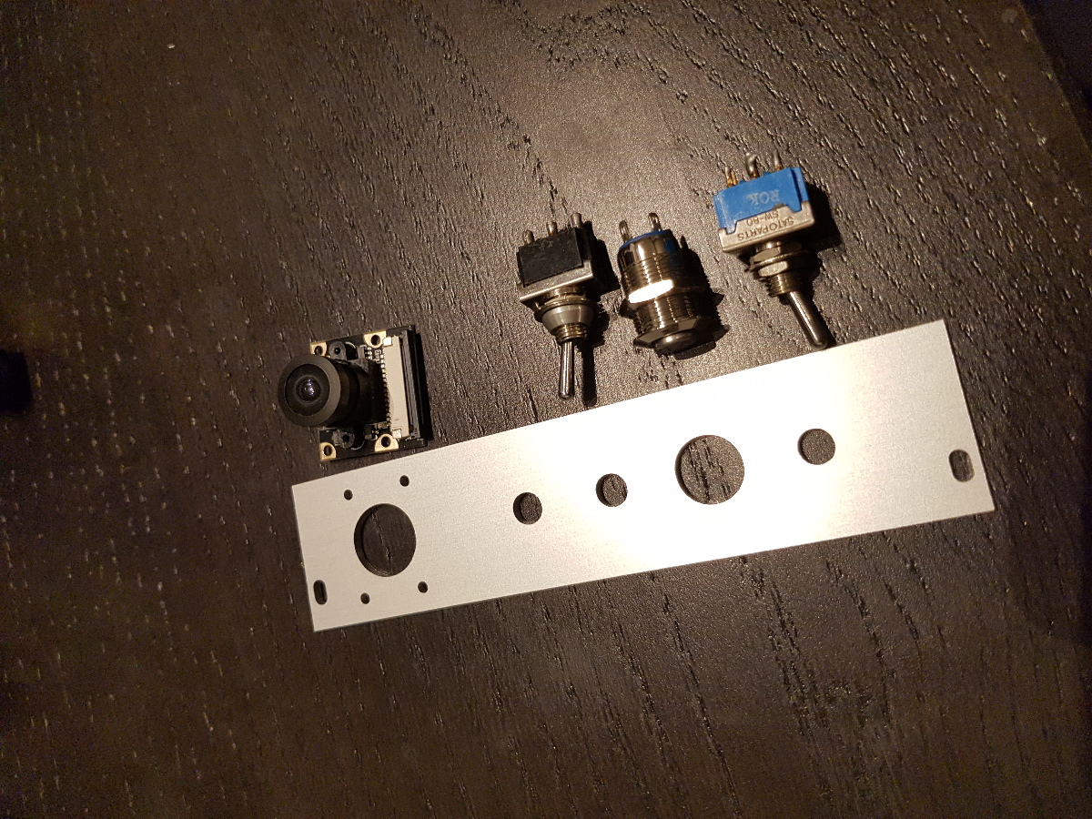
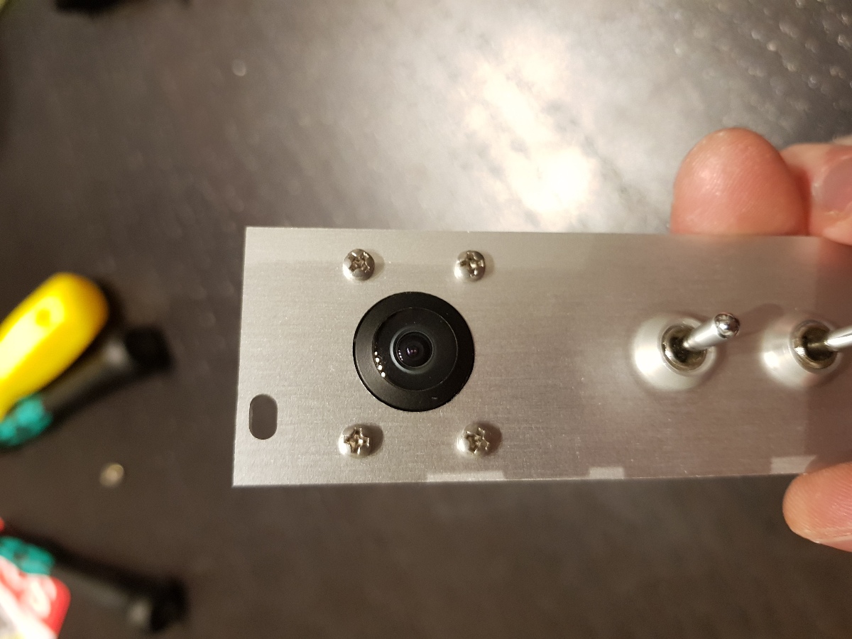
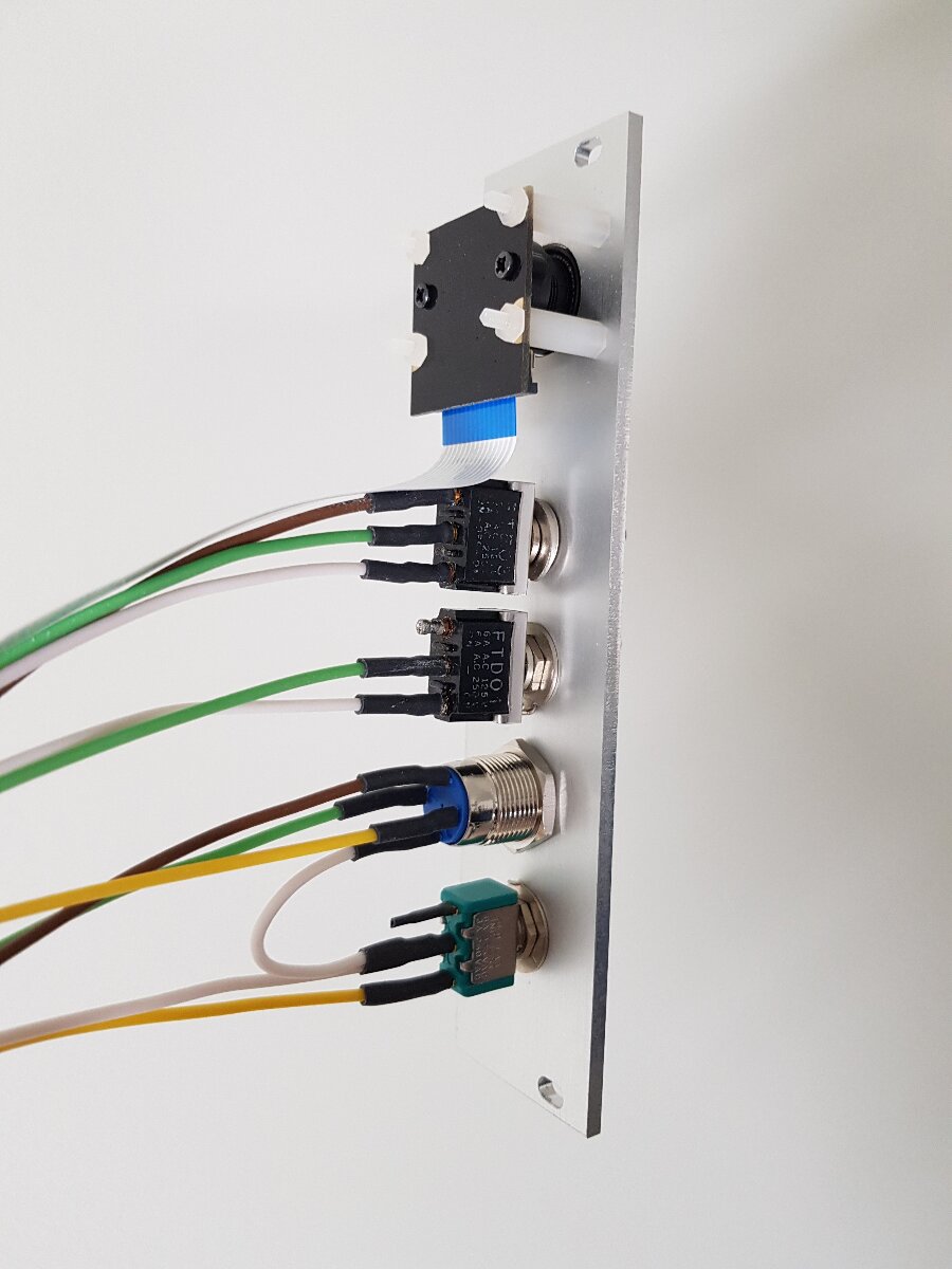
- The first panel has a wide angle CSI camera connected to the RPi providing a selfie view of the driver. Mostly for recording fun videos, but also useful for two-way video communication with the driver. There's also a switch and a button controlling the main power, and two switches connected to the Raspberry Pi originally intended to control motor direction, but was made redundant when I made the button panel next to the speaker.
- The screen is a 4" HDMI monitor with touch, connected to the Raspberry Pi. Originally, most controls were meant to be touch based, but as we all know mechanical buttons are so much better in a car, so that's why I added the button panel.
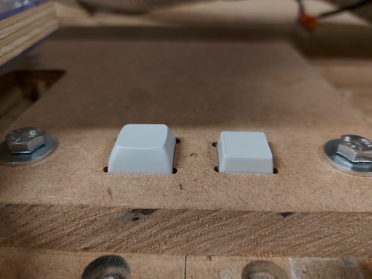
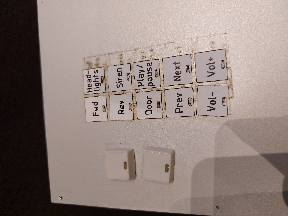
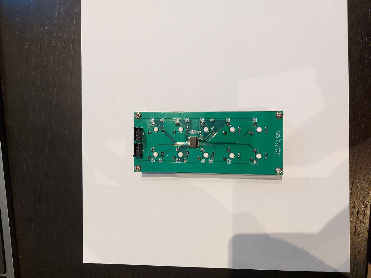
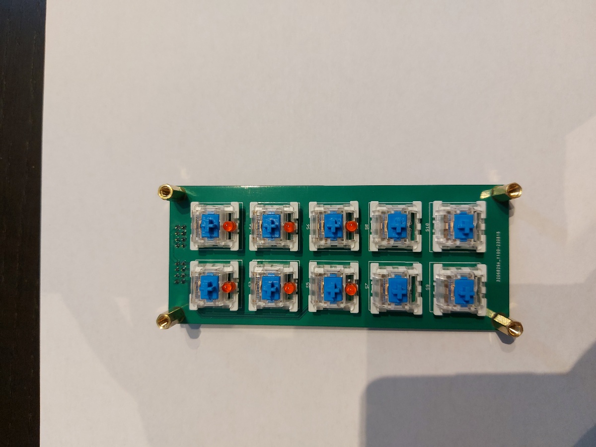
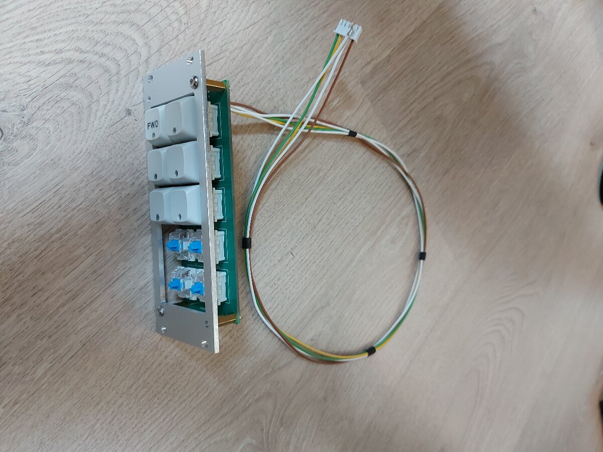
- The button panel has an array of 2 x 5 mechanical keyboard buttons with an LED indicator. An MCP23018 is used to interface these buttons and LEDs over I2C, and an additional interrupt line is nice to avoid continously polling for changes over I2C. The labels were printed on paper and then cut to size with a laser cutter.
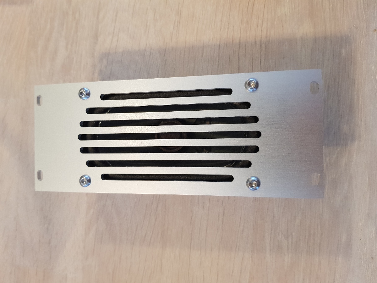
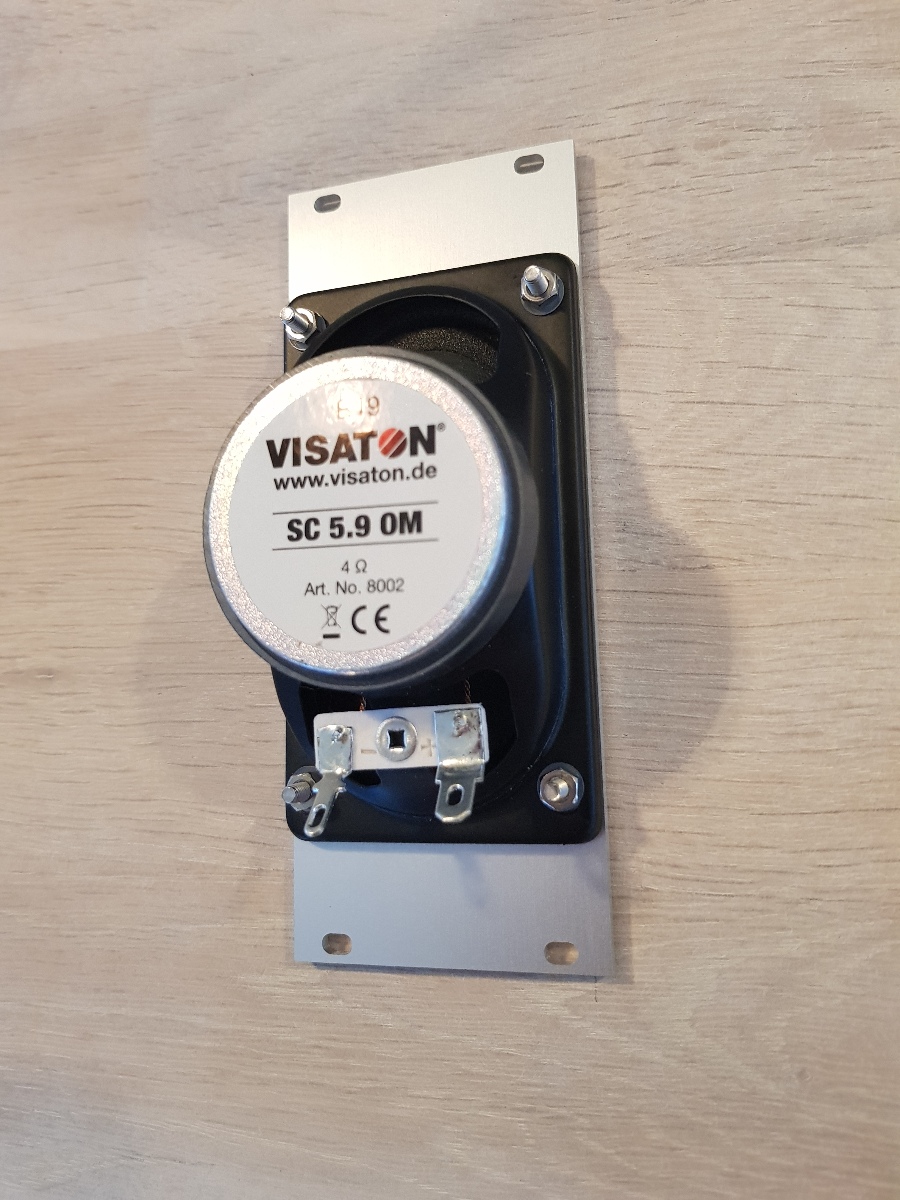
- The speaker is a simple Visaton full range speaker, working together with the subwoofer with a crossover frequency of 120 Hz. The crossover filter is realized in software using ALSA.

Other
The space under the seat was closed up with plywood and I mounted a tiny subwoofer in there as the dashboard mounted speaker had very limited low end output. This is also where the LiPo battery is located. A powerpole connector just in front of the seat rows is used for recharging.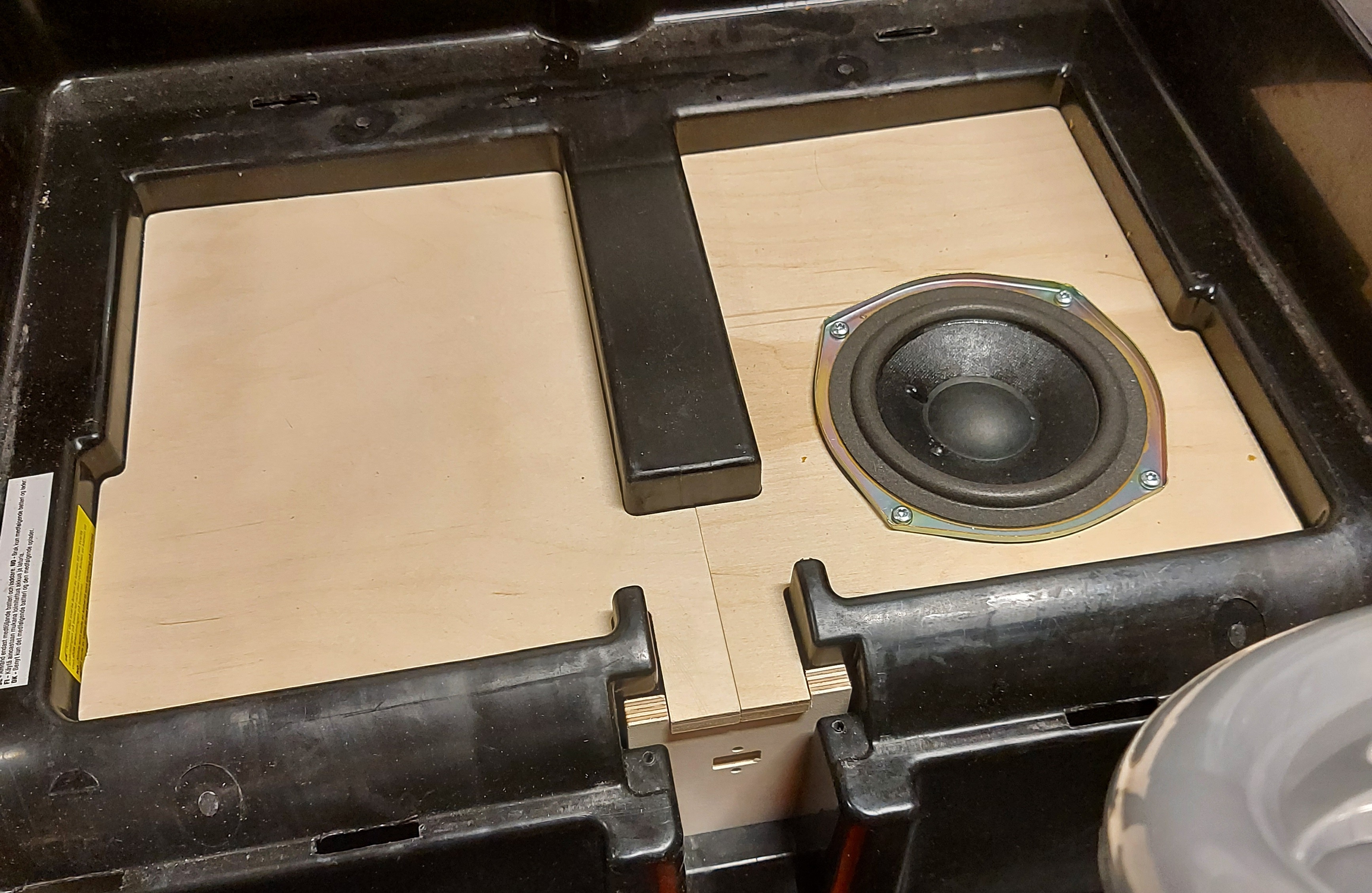
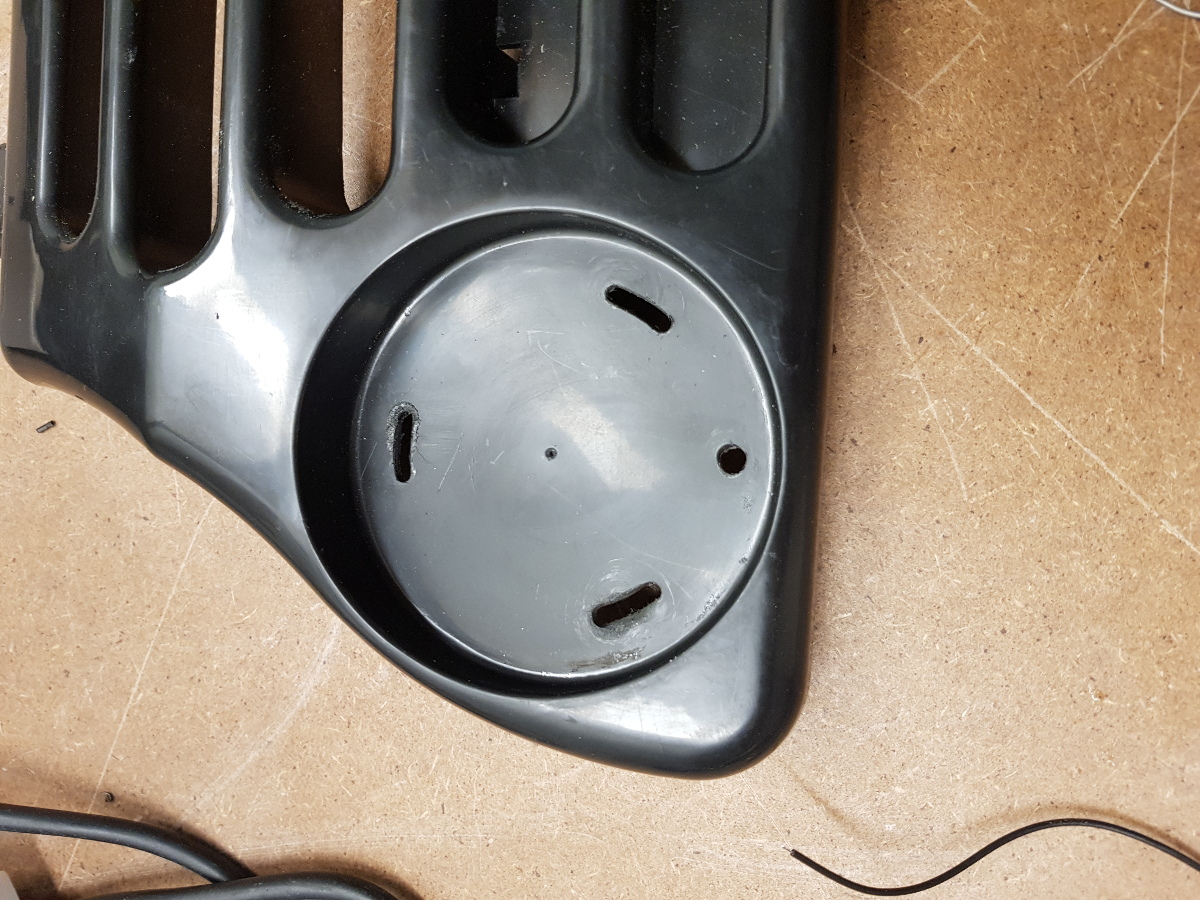
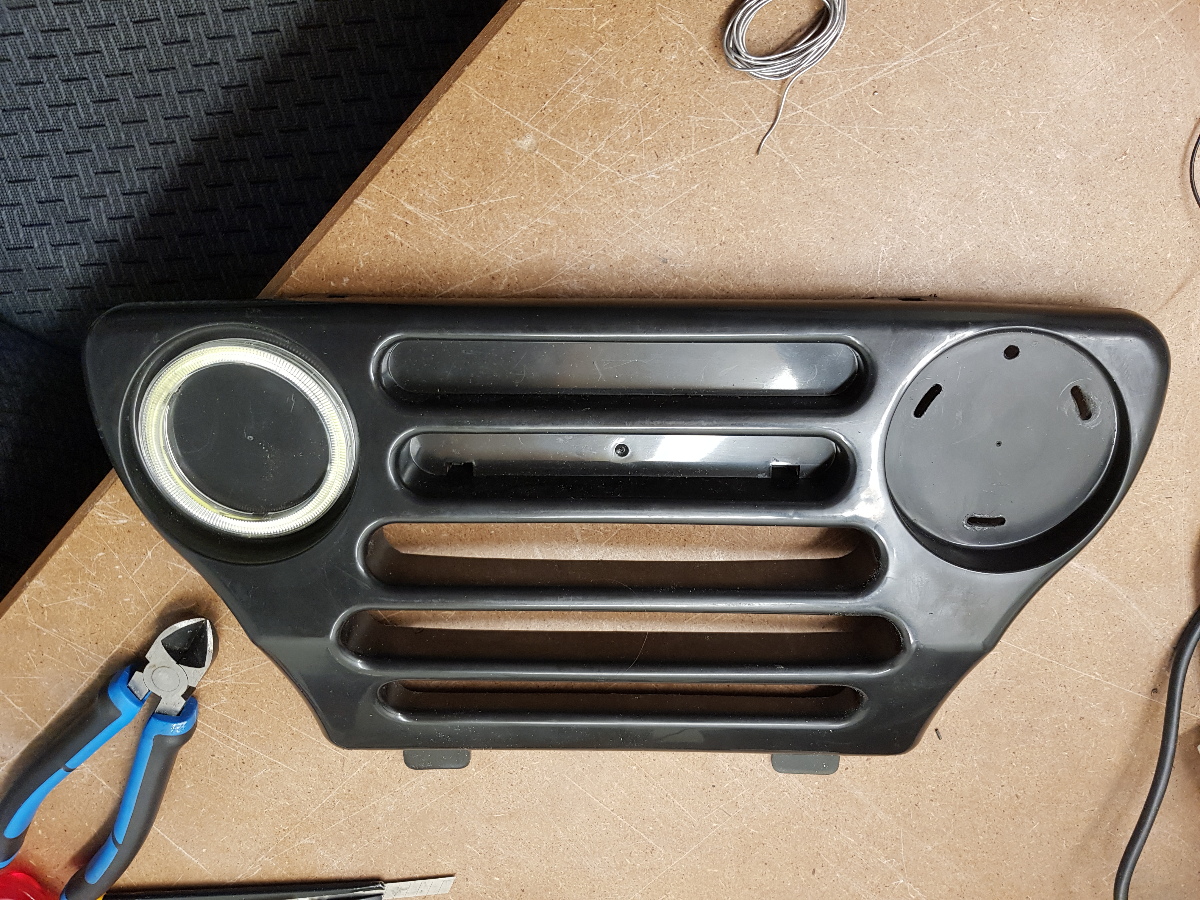
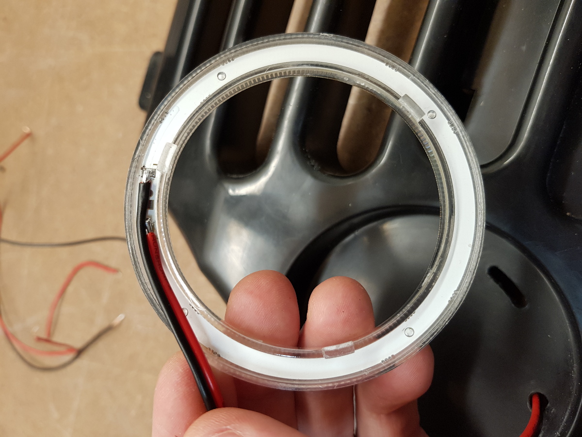
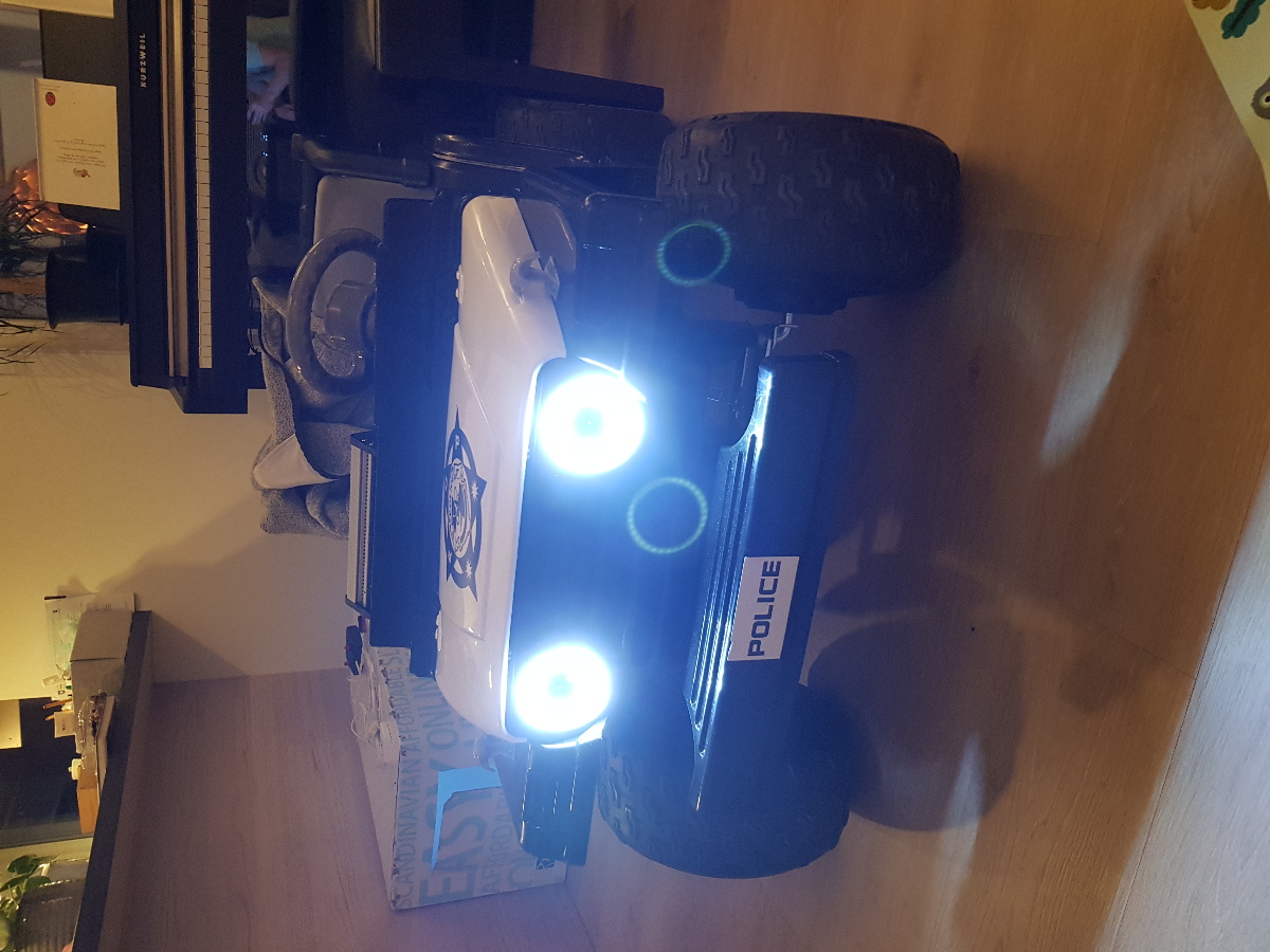
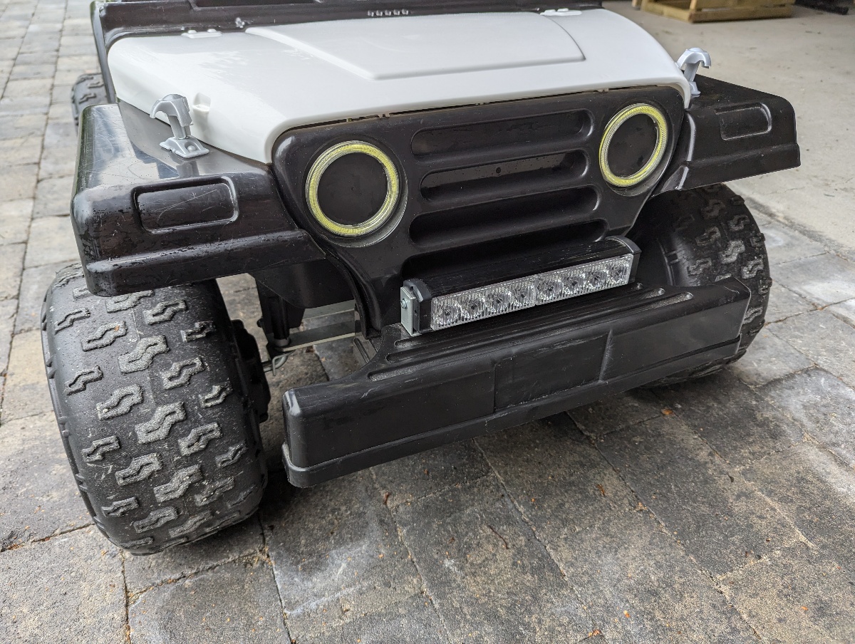
I also found some "Angel eye" LED lights on Aliexpress that fits perfectly in the recessed well where the original light stickers were: